Transport Analysis of Mobile Crushing-Screening Plants: Structural Study with FEA
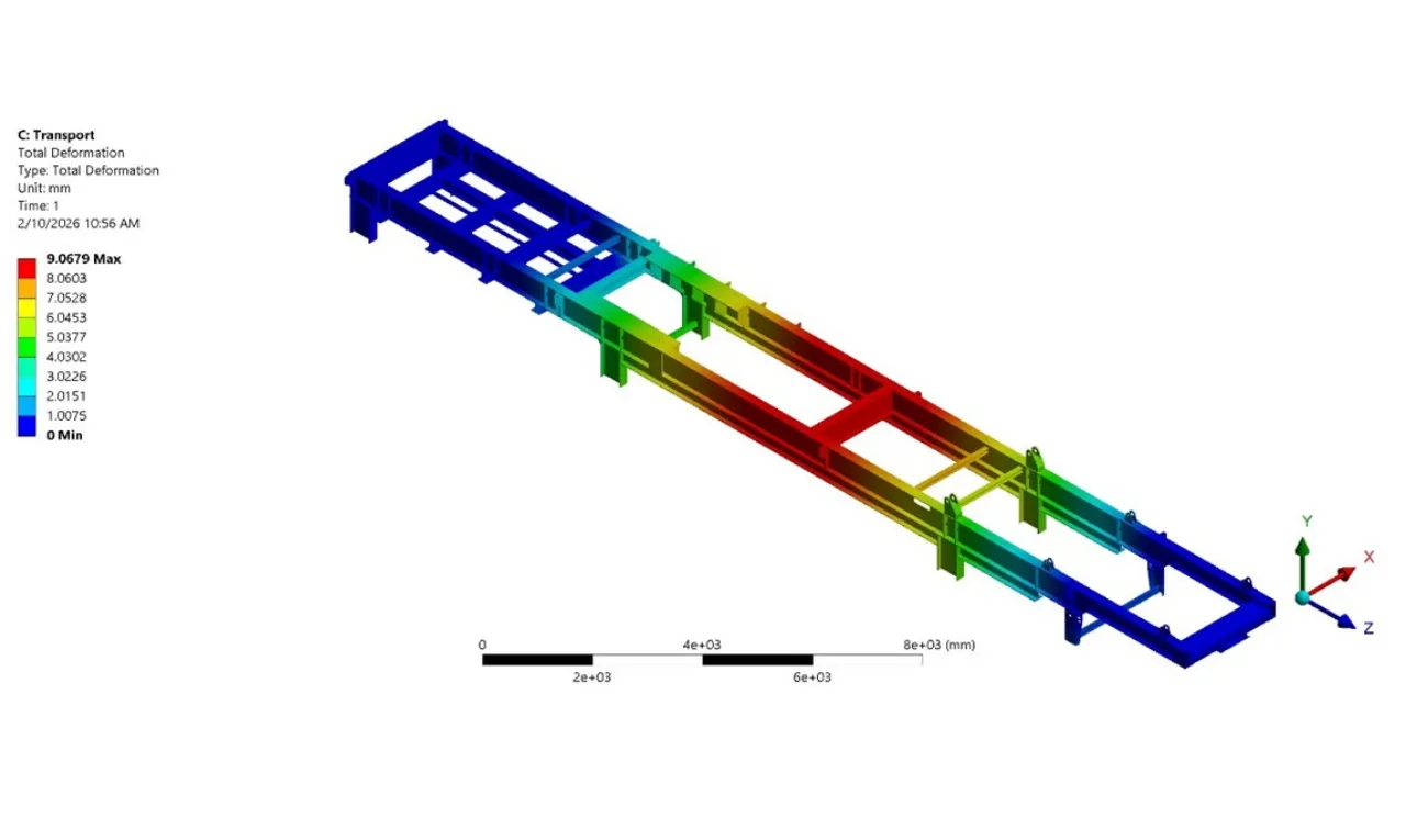
Mobile crushing and screening plants are critical production equipment that stand out for their advantage of portability between sites. However, this portability brings with it an important engineering question: is a plant weighing tens of tonnes structurally safe when it is subjected to road-induced dynamic loads during transport? In this article, we address how we examine the structural behaviour of mobile plants under transport conditions with Finite Element Analysis (FEA) and why this analysis is indispensable for the design process.
Why Is Structural Behaviour Different Under Transport Conditions?
Examining the structural behaviour of mobile crushing and screening plants in the transport position with Finite Element Analysis (FEA) is critically important, because the transport load case is completely different from the operating conditions. While the unit is in motion, it behaves like a long, flexible structure under road-induced vertical accelerations (usually 1.5–3 g), braking forces (about 0.8 g) and torsional effects caused by uneven ground. These combined bending and torsional effects cause stress concentrations in the chassis beams, axle connections and machinery equipment connections that cannot be accurately determined with simple hand calculations.
While operating on site, the plant sits on a fixed foundation and the loads are largely static. During transport, however, the structure is carried on a trailer with a limited number of connection points, far from a fixed (fully restrained) support. Every pothole in the road, every bend and every sudden braking applies dynamic forces to the structure in different directions. For this reason, the transport scenario is a load case that is independent of the operating scenario and requires a separate analysis.

Fatigue Damage and Cyclic Loads
Since transport loads are also cyclic, fatigue damage is a fundamental design criterion. Even if the maximum stresses stay below the yield strength, the loads repeated over dozens of shipments can lead to crack initiation at weld toes, beam junctions and connection brackets. FEA makes it possible to evaluate stress ranges under realistic acceleration scenarios and, by identifying the regions of the product that need improvement before production, makes it possible to prevent the damage that could occur — through operations such as increasing thickness, stiffening or improving the weld geometry.
Comparison of Transport and Operating Conditions
| Parameter | Operating Condition | Transport Condition |
| Vertical Acceleration | ~1 g (static) | 1.5 – 3 g (dynamic) |
| Longitudinal Force (Braking) |
None |
~0.8 g |
| Torsional Effect | Minimum | High (uneven ground) |
| Support Type | Fixed foundation / feet | Limited connection points |
| Load Character | Static + vibration | Cyclic dynamic |
| Critical Region | Production components, feed opening | Chassis, axle, weld seams |

Axle Load Distribution and Legal Compliance
In addition, transport analysis is necessary in terms of load distribution and compliance with legal regulations. In mobile plants with a mass averaging between 30 and 70 tonnes, the inertia forces that arise during braking and acceleration significantly change the axle and kingpin reactions. With FEA, the support reactions and structural behaviour under different transport scenarios can be predicted; thus, unnecessary weight increases are avoided while axle load limits are met. This approach reduces the risk of failure and, at the same time, increases the overall design reliability.
How Is FEA Applied in Transport Analysis?
Finite Element Analysis is an engineering method that divides a complex structure into thousands of small elements and numerically calculates the stress, deformation and reaction forces at each point. In the transport analysis of mobile plants, this method is applied in the following steps:
1. Geometric Modelling:The 3D CAD model of the plant in the transport position is prepared, together with the transport points, axle positions and kingpin connection.
2. Mesh Generation:The structure is meshed with finer element sizes in the regions where stress concentration is expected (weld seams, bracket junctions, axle connections).
3. Boundary Conditions and Loading:The kingpin and axle support conditions are defined; vertical acceleration (1.5–3 g), braking (0.8 g) and lateral loads (cornering, wind) are applied to the model as separate load cases.
4. Solution and Evaluation:The analysis results are examined through the von Mises stress distribution, deformation contours and support reaction forces. Critical regions are identified and the necessary design improvements are made.

MEKA's Approach
As MEKA Global, with our approach of designing long-lasting and reliable mobile plants, we carry out finite element analyses in our designs with great care and precision, minimizing the risks of structural failure that could occur both on site and during transport.
With our reference base of more than 4,500 plants and pieces of equipment installed in over 110 countries, we continuously improve our analysis models with real-world data obtained from the field in every new design. This discipline ensures that our customers have equipment that both operates efficiently on site and can be transported safely.
Conclusion
Transport analysis in mobile crushing and screening plants is a part of the design process that cannot be overlooked. A plant that operates flawlessly on site can be subjected to serious damage during shipment if it does not have sufficient structural safety under transport conditions. FEA is the most effective engineering tool that enables us to foresee and prevent these risks at the design stage.
Frequently Asked Questions
Why is transport analysis necessary in mobile crushing and screening plants?
The dynamic loads during transport (potholes, braking, cornering) are very different from the static loads encountered on site. In a unit weighing 30–70 tonnes, these forces can cause critical stresses in the chassis and axle connections. Transport analysis makes it possible to identify these risks at the design stage.
Which load scenarios are used in FEA transport analysis?
Typical scenarios include vertical road accelerations (1.5–3 g), braking forces (0.8 g), lateral wind and cornering effects, and torsional loads caused by uneven ground. These scenarios are usually determined on the basis of standards such as EN 12999 and ISO 8686 and of field experience.
How is fatigue damage prevented during transport?
Fatigue damage is prevented by evaluating stress ranges with FEA and thereby identifying critical regions. Increasing thickness, adding stiffeners, improving the weld geometry and optimizing connection details are the most common preventive measures.
What is Finite Element Analysis (FEA)?
FEA (Finite Element Analysis) is a simulation method that divides complex engineering structures into thousands of small elements and numerically calculates the stress, deformation and forces at each point. It makes it possible to detect design weaknesses before producing a physical prototype.
MEKA GLOBAL