Vibrating Feeder Working Principle, Amplitude and Capacity

In crushing and screening plants, hopper feeders are generally used so that secondary and tertiary crushers are fed continuously, evenly and at the same capacity.
If these crushers are not fed evenly, they do not run at the required performance. For example, when cone crushers are not fed evenly and their crushing chambers are not full, wear increases considerably and bearing life shortens because of unbalanced loading. In vertical shaft impactors (VSI), the rock box does not form and crushing performance drops considerably.
This article covers the variables used to calculate how vibrating feeders move material and what capacity they deliver. Feeder types and selection for the whole plant are covered in a separate guide.
How a Vibrating Feeder Actually Moves Material
In vibrating grizzly feeders, the task of the drive (exciter) assembly is to apply to the feeder body an excitation force whose magnitude varies sinusoidally, at a magnitude and angle that give the material the travel speed it needs. This is the vibrating feeder working principle the calculations in this article are built on.
In vibrating grizzly feeders, the excitation force can be provided by vibrating motors (vibro motors), and other methods are also used. Considering these methods, the drive assemblies of vibrating grizzly feeders can be grouped as follows:
Twin eccentric shaft drive assemblies
Twin mechanical vibrator drive assemblies
Twin vibrating motor drive assemblies
Exciter-driven vibration assemblies
For the feeder to provide the required feed capacity, the drive assembly must give the material to be fed the required material speed. The actual material travel speed is:
v = r · ω · cos α · √(1 − 1/Γ²) · μβ · μs · μm
Γ = (r · ω² · sin(α + β)) / (g · cos β)
- Γ: throw number; 2.5–3.5 are suitable values for vibrating grizzly feeders
- r: vibration amplitude along the line of vibration, mm
- ω: angular velocity, rad/s (see Frequency and Speed)
- α: angle of the line of vibration to the horizontal, selected between 35° and 55°; 35° is the most widely applied throw angle
- β: angle of the trough plane to the horizontal
- g: gravitational acceleration, 9.81 m/s2
- μβ, μs, μm: slope factor, material size factor, coefficient related to the moisture content and contamination of the material (see Slope and Material Behaviour and Calculating Capacity)
Amplitude, Frequency and Slope: The Three Levers
This section takes three of the variables in the speed formulas one by one: the vibration amplitude r, the exciter speed n and the trough slope β.
Vibration Amplitude
In the speed formulas, r is the vibration amplitude along the line of vibration, in mm. It also appears in the throw number Γ and, in metres, in the static-moment and exciting-force formulas under Calculating Capacity.
Measuring the amplitude on a running feeder is covered in our service guide.
Frequency and Speed
In vibrating grizzly feeders, n, the revolutions per minute of the exciter element, is selected between 650 and 1000 rpm depending on the type of exciter mechanism used. It enters the speed formulas through the angular velocity:
ω = π · n / 30
- ω: angular velocity, rad/s
- n: revolutions per minute of the exciter element, rpm
For under-hopper vibrating feeders, Table 5 shows the recommended material speed values.
| Material size, mm | Vibrating deck angle, degrees | Material speed, m/s |
|---|---|---|
| < 100 | 8–12 | 0.28 |
| 100–300 | 4–8 | 0.25 |
| > 300 | 0–4 | 0.22 |
Table 5. Recommended material speed values
Slope and Material Behaviour
β is the angle of the trough plane to the horizontal. It enters the speed formulas through the slope factor μβ. For vibrating grizzly feeders, the slope factor μβ is taken as:
- μβ = 1.15 for β = 3°
- μβ = 1.3 for β = 5°
- μβ = 1.48 for β = 8°
- μβ = 1.6 for β = 10°
For under-hopper vibrating feeders, μβ, the feeder slope angle factor, is taken from Table 4.
| Feeder slope angle β, degrees | Slope angle factor μβ |
|---|---|
| 0 | 1 |
| 2 | 1.02 |
| 4 | 1.05 |
| 6 | 1.10 |
| 8 | 1.19 |
| 10 | 1.30 |
| 12 | 1.49 |
| 14 | 1.72 |
Table 4. μβ slope angle factor
How material size, moisture and clay enter the calculation is covered in the next section.
Calculating Capacity
The vibrating feeder capacity calculation is given below as volumetric capacity for vibrating grizzly feeders, followed by the material speed formula for under-hopper vibrating feeders and the exciting force and drive power.
Vibrating Grizzly Feeders: Volumetric Capacity
The volumetric capacity is:
Qv = 3600 · v · B · H
- Qv: volumetric capacity, m³/h
- v: actual material speed, m/s
- B: inner width of the feeder, m
- H: bed depth at the feeder discharge, m
The material size factor μs is taken, based on experience, as:
- μs = 1 for sand
- μs = 0.8–0.9 for material sizes up to 150 mm
- μs = 0.6 for material larger than 150 mm
μm, the coefficient related to the moisture content and contamination of the material, is taken as:
- μm = 1 for dry material
- μm = 0.8 for moist material
- μm = 0.6 for moist and clayey material
In the calculations, H, the bed depth at the feeder discharge, is taken on the basis of certain assumptions that depend on experience, as follows:
- H ≤ 0.2 B for sand and fine gravel
- H ≤ 0.3 B for run-of-mine material up to 150 mm
- H ≤ 0.5 B for material larger than 150 mm
In vibrating grizzly feeders, the theoretical travel speed can be determined approximately from Graph 1, which gives it for a throw angle of α = 45° at different amplitude values.

Under-Hopper Vibrating Feeders: Material Speed
For under-hopper vibrating feeders, the material speed is calculated with the formula:
v = r · ω · cos α · √(1 − 1/Γ²) · μβ · μh · μs · μm
In this formula:
- μh: bed depth factor, taken from Graph 2
- μs: friction factor, the coefficient that expresses the friction between the material and the trough; μs = 0.85 is taken
- μm: material property factor, varies between 0.8 and 1; the small values are for light, moist, sticky materials
- μβ: feeder slope angle factor, taken from Table 4

Exciting Force and Drive Power
Starting from the principle that the static moment of the vibrating feeder body must be equal to the static moment of the exciter system:
G · r = G1 · (R − r)
- G: weight of the vibrating body, kg
- r: amplitude, m
- G1: total of the eccentric masses, kg
- R: distance from the centre of gravity of the eccentric masses to the axis of rotation, mm

With the help of this formula, the static moment G1R of the exciter system is determined, and the design is made according to the type of exciter system to be used.
Exciting force:
Fu = (mt + me) · 4π² · ft² · r
- Fu: exciting force, N
- mt: weight of the trough (excluding the exciter assembly), kg
- me: weight of the exciter assembly, kg
- ft: exciter frequency, rev/s
- r: amplitude, m
Drive power:
P = Fu · vtm
- P: drive power, Nm/s (or watt)
- Fu: exciting force, N
- vtm: mean trough speed, m/s
vtm = (2/π) · vtmax = 4 · r · ft
vtmax = r · ω
- vtmax: maximum trough speed, m/s
- vtm: mean trough speed, m/s
- ft: drive frequency, rev/s
Note: For under-hopper vibrating feeders, the exciting force and motor power are calculated as in vibrating grizzly feeders.
The Hopper and Feed Arrangement
Under-hopper vibrating feeders are generally placed under a hopper with a capacity of 10–20 m³. The body of a hopper vibrating feeder is either suspended from the hopper together with coil springs, or sits together with coil springs on a fixed frame.

When the Feeder Also Screens: Vibrating Grizzly Feeders
In primary crushers, material smaller than the crusher discharge setting entering the crusher is generally not desired, because of crusher performance. It is also desired that clay and similar material in the run-of-mine feed is separated from the plant, that is bypassed, before it enters the crusher. For this reason, thanks to the grizzly screening section with one or more steps at the front of the feeder, fine and dirty material that should not enter the crusher is bypassed and kept out of the crusher.
The drive assemblies and speed formulas given above are those of the vibrating grizzly feeder, so the vibrating grizzly feeder working principle is the one described in the earlier sections.
In crushing and screening plants, in some cases the feeder and grizzly sections are separated and used as separate units, to screen out the fines in the feed more efficiently than a vibrating grizzly feeder does, raising crusher performance and reducing wear costs. Driving the grizzly screen independently of the feeder makes it possible to set variables such as the throw angle, vibration amplitude and angular velocity independently of the feeder, so screening becomes more efficient.
The grizzly section should have at least two steps. This way, the material drops and turns as it passes from one step to the next, and clay and other foreign material stuck to it separates and goes to the bypass line. When needed, the grizzly screen can be designed as a double deck, so that unwanted dirty material can be removed from the plant without using a separate bypass screen.
Grizzly spacing, scalping and grizzly area are covered in a separate guide.
Springs and Exciter Mounting
The vibration assemblies are bolted to the main body. Because of the magnitude of the excitation force, the connection must be made over a wide area and quite rigidly.
The body of a hopper vibrating feeder is either suspended from the hopper together with coil springs, or sits together with coil springs on a fixed frame.
Spring systems and modal analysis for vibrating feeders are covered in separate articles.
MEKA Vibrating Feeders
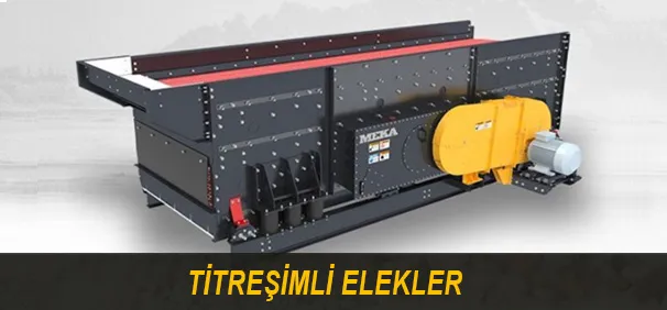
The feeder types discussed in this article are presented on MEKA's product pages: vibrating feeders, vibrating grizzly feeders and pan feeders with grizzly scalper. MEKA's apron feeders have their own product page.
Frequently Asked Questions
What is the amplitude of a vibrating feeder?
In the calculations in this article, r is the vibration amplitude along the line of vibration, given in mm in the speed formulas. It appears in the throw number Γ, in both material speed formulas, in the static-moment formula and in the exciting-force formula.
How does the deck slope affect material speed?
The slope factor μβ is a multiplier in the material speed formula, and in both sets of values it rises with the slope angle. For vibrating grizzly feeders, μβ is 1.15 at β = 3°, 1.3 at 5°, 1.48 at 8° and 1.6 at 10°; for under-hopper vibrating feeders, Table 4 gives μβ from 1 at 0° to 1.72 at 14°. In Table 5, the recommended vibrating deck angle is 8–12° for material below 100 mm, 4–8° for 100–300 mm and 0–4° above 300 mm.
Can a vibrating feeder handle wet or sticky material?
Moisture and clay enter the calculation through the factor μm. For vibrating grizzly feeders, μm is taken as 1 for dry material, 0.8 for moist material and 0.6 for moist and clayey material. For under-hopper vibrating feeders, the material property factor μm varies between 0.8 and 1; the small values are for light, moist, sticky materials.
Why is the actual material speed lower than the theoretical speed?
In the calculation method above, the actual material travel speed is the theoretical speed multiplied by the material size factor μs and the moisture and contamination coefficient μm. In the values given, both factors are 1 or lower: μs is 0.6 for material larger than 150 mm, and μm is 0.6 for moist and clayey material.
MEKA GLOBAL