Belt Conveyor Calculations
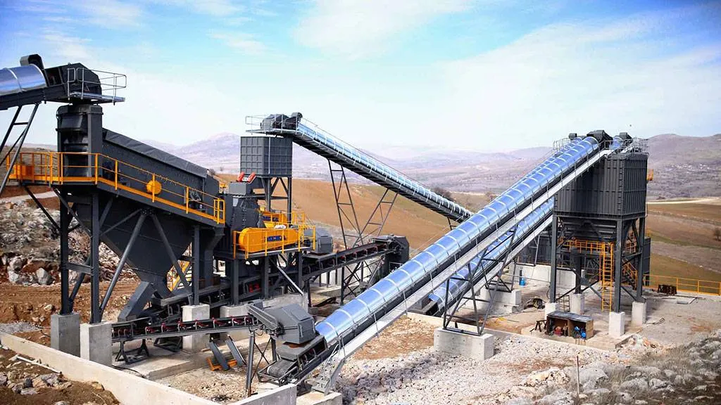
Belt conveyor calculations are a critical process for optimizing efficiency and operational costs in industrial plants. Correctly performed calculations determine belt width, speed, carrying capacity and power requirements, ensuring that the system operates at maximum performance. These calculations must be carried out meticulously according to the type of material, the conveying distance and the angle of inclination, and must be planned so as to minimize both energy consumption and maintenance costs. Approaching belt conveyor calculations with a professional method helps businesses maintain their competitive advantage and achieve long-term success.
Belt Width and Belt Conveyor Speed
As a reference for belt width selection, use Table 4, and for conveyor speed selection, Table 5 is used as a reference.
CapacityThe volumetric capacity values in belt conveyors, V, are given in m³/hour according to belt width in Table 1.
These values are given for a 20° dynamic surcharge angle, a 35° side (trough) idler angle, and belt conveyors operating in the horizontal position.
In this case, the belt conveyor capacity is:Q = V × δ × cosα × CF
Q:Capacity, t/h
V:Volumetric capacity, m³/hour, Table 1
δ:Material bulk density, t/m³
cosα:Cosine of the belt inclination angle, Table 2
CF:Capacity factor, Table 3


Forces the Drive Pulley Must Transmit to the Conveyor Belt
The conveyor drive system must transmit the following forces to the conveyor belt:
- F₁, the force required to set the empty conveyor belt and the conveyor idlers in motion
- F₂, the force required to convey the material along the conveyor
- F₃, the force required to lift the material
- F₄, the friction forces applied by the additional belt conveyor components (belt scrapers, side-skirt scrapers, etc.)

F₁: kg
C: Length coefficient, taken from Graph 1.
𝑓: Idler friction coefficient. Depending on the idler design it varies between 0.017 and 0.04. Its standard value is f0,020-0,025In very dusty environments and at low temperatures, 0,035-0,04 is taken.
L: Distance between the conveyor pulley axes, m
B: Conveyor inclination angle, (°)
β: Conveyor inclination angle, (°)
q: Weight of the conveyor belt, kg/m²
qᵣ¹, qᵣ¹¹: Weight of the rotating parts of the carrying and return idler groups, kgTable 11 is used.
a¹, a¹¹: Distance between the carrying and return idler groups respectively, m
F₂ — the force required to move the material along the conveyor

F₂,The force required to move the material along the conveyor, kg
Q:Capacity, tonnes/hour
v:Conveyor speed, m/s
F₃ — the force required to lift the material,

F₃:The force required to lift the material, kg
H:Amount by which the material is raised, m
F₄ — the force required to overcome the resistance of the loading chutes or side scrapers

F₄:The force required to overcome the friction of the loading chutes or side plates, kg
fₛ:Coefficient of friction between the material and the side skirts, Table 11 is used.
lₛ:Length of the loading chute or skirt, m
hₛ:Material height, m
hₛ = 0,1 B is taken.
B:Belt width, m
NOTE: If there is rubber under the side skirts or the loading chute, for each metre of rubber length 4.5 kg/m of additional force is added.
The total required force that the drive system must transmit to the conveyor belt:

Required motor power:

F:Total force that the drive system must transmit to the conveyor belt, daN
v:Conveyor speed, m/s
ɳ :Mechanical efficiency. In the calculations, ɳ0,90 is appropriate to use.
Tensions in the Conveyor Belt:

Equations Used for the Tensions:

µ :The coefficient of friction between the pulley and the conveyor belt. For uncoated pulleys µ = 0.25, and for rubber-coated pulleys µ = 0.35 is taken.
α :The wrap angle of the belt around the pulley, radians
Pulley Diameter Calculation in Belt Conveyors
Drive pulley diameter:D = Cᴛᵣ × sₖ
D:Minimum pulley diameter, mm
sₖ:Carcass thickness (Table 8); for steel-cord belts, the cord diameter, mm
Cᴛᵣ:Coefficient
| Carcass warp material | Cᴛᵣ |
| B (cotton) | 80 |
| P (polyamide) | 90 |
| E (polyester) | 108 |
| St (steel) | 145 |
Cᴛᵣ Coefficients
Tables and Graphs Used in Conveyor Calculations


NOTE:The weight of one square metre of a 1 mm thick rubber cover is 1.2 kg.


RADIAL CONVEYOR STOCKPILES

NOTE:
- The values given in the graph above are for a static surcharge angle of α = 40°.
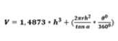
- Total stockpile volume:

MEKA GLOBAL