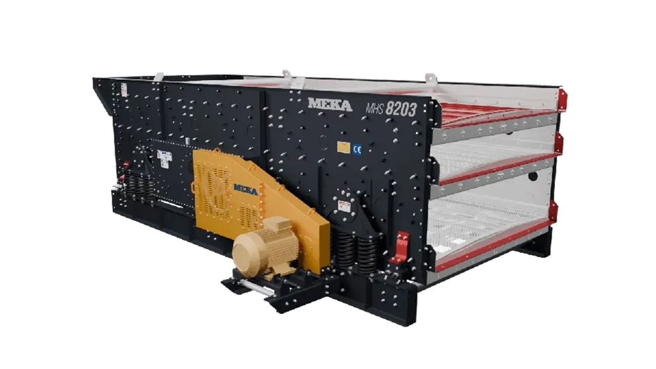
Reasons for Using Circular-Motion Conventional and 3-Shaft Controlled Elliptical Vibrating Screens as the Main Distribution Screen
Vibration Patterns of Screens
Circular-motion vibrating screens use a circular movement for screening. Gravity is needed for the material to advance over the screen mesh. For this reason, these screens are designed with an inclination. As the material particle advances over the screen panel, it makes a tumbling motion. This motion prevents the particle from becoming lodged (pegging) in the screen aperture and enables smaller particles to be screened.
Linear-motion horizontal (or very low-incline) screens use a back-and-forth movement at a positive angle to the vertical. The screen panel lifts the particle and causes it to fall at a point further along. This motion enables the material particle to advance over the screen panel. Because the screen is horizontal, the material particle falling in the vertical direction uses the entire screen aperture for screening. The screening of the undersize material is thus made easier.
Oval-motion vibrating screens, on the other hand, combine the rotating feature of circular-motion vibrating screens with the feature of using the entire screen aperture of linear-motion vibrating screens. Thus their screening efficiency and screening capacity are higher than those of circular- and linear-motion vibrating screens of the same size.

Reasons for Preferring Oval-Motion Vibrating Screens
- High capacity
- The controllability of the vibration parameters
- A robust and long-lasting structure
are the most important reasons for preferring oval-motion controlled vibrating screens.
High Capacity
The capacity formula for vibrating screens is as follows. This formulaVSMA (the American Vibrating Screen Manufacturers Association) formula.
A:The unit screening capacity of the screen,TPH/ft²
The factors used in this formula:
B:Basic capacity,TPH/ft²— Graph 1
S:Inclination factor — Graph 2
D:Screen deck position factor — Graph 3
V:Oversize material ratio factor — Graph 4
H:Half-size factor of the screen aperture — Graph 5
T:Screen aperture shape factor — Graph 6
K:Material condition factor — Graph 7
Y:Washing factor — Graph 8
P:Material shape factor — Graph 9
W:Weight factor — Graph 10
O:Open area factor — Graph 11
F:Screen efficiency factor — Graph 12


Recently, especially after 3-shaft oval-motion vibrating screens came into use, the VSMA formula has been modified as follows.
TYP:Vibration stroke type factor — Graph 13
STR:Stroke length factor — Graph 14
TIM: Vibration angle factor — Graph 15
RPM: Vibration speed factor — Graph 16
NEA:Near-size factor — Graph 17
BED:Material bed thickness factor — Graph 18
These factors are taken from the following graphs.


The most important of these factors is the TYP vibration-pattern factor.
Graph 13 shows us the TYP factors. As can be seen from this, in oval-motion vibrating screens, solely because of the vibration pattern,%12 there is a capacity increase.
In addition, Figure 2 explains the additional capacity that arises because the screen operates horizontally. We also see this from the S – Screen inclination factor shown in Graph 2. As can be seen in this graph, in a horizontal screen compared with an inclined screen, %10 a capacity increase is achieved.
If we take the effect of all these factors into account, the capacity of an oval-motion screen is about 30% higher than that of an inclined, circular-motion screen of the same size.
The Controllability of the Vibration Parameters
In 3-shaft oval-motion vibrating screens:
- The vibration stroke length
- The vibration angle
- The vibration frequency
parameters can be easily changed according to the properties of the material to be screened. In other screens, it is not possible to change the vibration angle in particular. Yet changing the vibration angle according to the structure and grading of the material to be screened would make a great contribution to both capacity and screening efficiency. We also see this from Graph 14 STR, Graph 15 TIM and Graph 16 RPM graphs.
Figure 3 shows the change in stroke size and angle according to the properties of the material.
Figure 4 shows how the vibration frequency is changed.
Table TB2-1 shows the change in stroke length with the addition of cylindrical weights.


As a result, in a 3-shaft oval-motion vibrating screen, the controllability of the vibration parameters according to the material property increases the screen efficiency by 5–10% compared with other screens of the same size.
A Robust and Long-Lasting Structure
Thanks to the special bearing design, since the inner ring of the bearings stays fixed and the outer ring rotates, the loads are distributed over a wide area, which increases the bearing life. In addition, it has a very robust body structure.
As a result, good design and a robust body structure considerably increase the screen life.
Reasons for Preferring Circular-Motion Vibrating Screens
Despite all their disadvantages, circular-motion vibrating screens of the same size and number of decks have lower manufacturing, maintenance and operating costs. For this reason, they are preferred by many aggregate producers, especially in plants with relatively low capacities.
References
- TEREX CEDARAPIDS TSH Horizontal ScreensForm 25524
- TEREX CEDARAPIDS ElJay Legacy Series ScreensBulletin EJLS-1
- Titreşimli Besleyiciler ve Titreşimli Elekler (Vibrating Feeders and Vibrating Screens)Suphi Yavuz, 2017, Gece Kitaplığı, ISBN 978-605-288-214-6
- Technical Paper T-JCI-205Screen Capacity Paper by Larry Olsen & Bob Carnes
Suphi Yavuz
Senior Mechanical Engineer
Chamber of Mechanical Engineers registration no: 9219
MEKA GLOBAL