Primary Jaw Crusher or Primary Impact Crusher?
Choosing the Right Primary Crusher for Aggregate Production
Introduction
Many factors influence the choice of a primary crusher in aggregate production. This article first reviews the working principles, force analyses, capacity and power calculations of the two main primary crusher types — the primary jaw crusher and the primary impact crusher — and then discusses the criteria that should guide the selection between them when designing a crushing and screening plant. Particularly in concrete and road aggregate production, the choice between a primary jaw crusher and a primary impact crusher directly affects the plant's capital investment, wear-related operating costs, and final product quality.
Jaw Crusher: Working Principle, Force Analysis, and Capacity and Power Calculation
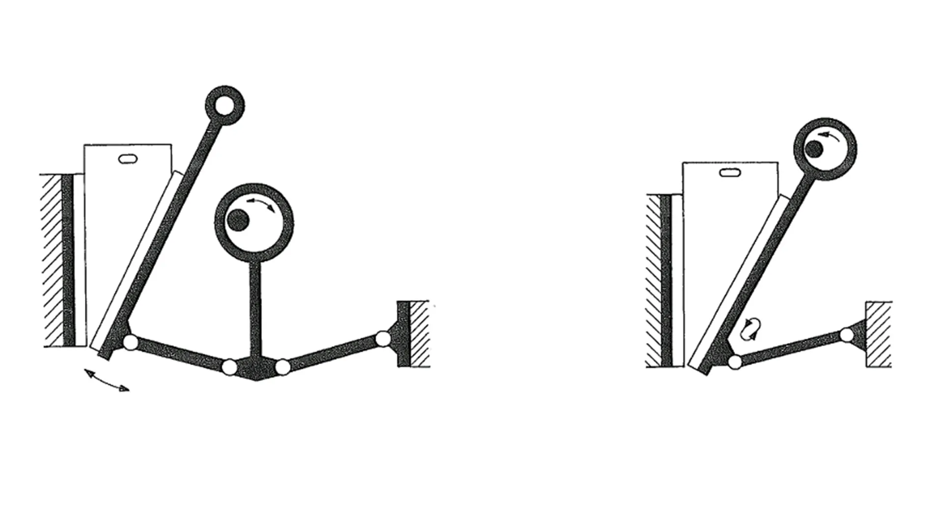
The function of any crusher is to apply a force capable of breaking the feed material. In jaw crushers, this force is a compressive force. Structurally, jaw crushers come in two configurations:
- Single toggle jaw crushers
- Double toggle jaw crushers

Figure 1 shows schematic views of both double toggle and single toggle jaw crusher mechanisms. In single toggle crushers, every point on the movable jaw traces an elliptical orbit as a consequence of the underlying four-bar linkage mechanism. The material is therefore subjected not only to compressive force, but also to shear, friction, and abrasive stresses.
In double toggle crushers, by contrast, every point on the movable jaw moves linearly along an axis perpendicular to the jaw face. Only compressive force is therefore applied to the material. Because of this, double toggle jaw crushers are typically used in the mining sector for very hard and highly abrasive ores. Their relatively high operating cost per unit of capacity means they are rarely used in the aggregate industry.
Jaw crushers used in aggregate plants are almost exclusively single toggle units. Mechanically, these are four-bar linkages. Figure 2 shows a cross-section of a single toggle jaw crusher with its main components; Figure 3 presents a schematic of its kinematic and force analysis.


r2 is the eccentricity of the crusher's eccentric shaft and forms the 2nd link of the mechanism. The distance between the tip of the eccentric and the inner face of the toggle plate seat, r3, forms the 3rd link. This link lies on the pitman to which the movable jaw is mounted.
The 4th link is the toggle plate, of length r4, The 1st link, r1, is the fixed distance between the inner face of the toggle plate seat (inside the adjustment block) and the axis of the main bearing assembly of the eccentric shaft on the frame.
When the eccentric shaft is driven at n RPM by a motor of power P, the torque on the shaft is:
The forces and torques on the links of the mechanism are then:
If, during one 3600 rotation of the eccentric shaft (and therefore of link r2), link r3 — which carries the movable jaw via the pitman — rotates by Δθ3 about its center O3, then the crushing force applied within the crushing chamber is:
where Lp is the displacement of the jaw in the direction perpendicular to the jaw face, and Δθ3 is the change in angle θ3 over one period of motion, expressed in radians. Figure 4 shows a schematic of the jaw tip's trajectory.

The crushing force can be calculated either through the kinematic and force analysis described above, or by using empirical formulas developed by various researchers. The most widely used of these is the Bonwetsch formula:

Where:
Fk: Crushing force, kN
P: Motor power, kW
r2: Eccentricity of the shaft, mm
n: Rotational speed of the eccentric shaft, RPM
For crushers with a feed opening larger than 1200 × 800 mm, it is more appropriate to take approximately 70% of the rated motor power as the value of P.
Jaw Crusher Capacity
Rose & English formula:
QM: Maximum capacity at the critical speed, TPH
Critical speed:
If the crusher operates at a speed n other than the critical speed, the actual capacity is:
LT: Stroke
LT = LMAX - LMIN
ρS: Specific gravity of the feed material, t/m³
f(PK), f(β): Values read from Graph 1
SC: Surface characteristic coefficient, 0.5 - 0.7
W: Length of the crusher feed opening, m
R: Reduction ratio
LMIN: Closed Side Setting (CSS) of the discharge opening
LMAX: Open Side Setting (OSS) of the discharge opening
G: Maximum particle size entering the crusher


Graph 1 — f(PK) and f(β) values
dMAX, dMIN, dAVG: Maximum, minimum, and average particle sizes in the feed
Figure 6 illustrates the operating geometry of a jaw crusher. The material trapped in the wedge between levels A and B is the material that will leave the crusher during the next return stroke of the movable jaw — that is, during the next half-cycle.
The vertical distance h between levels A and B is given by:
By combining the Rose & English formula with the Bond formula, the power requirement of a jaw crusher can be expressed as:
Wi: Bond Work Index
Impact Crusher: Working Principle, Force Analysis, and Capacity and Power Calculation
Figure 7 shows the main components of a horizontal shaft impact crusher. In summary, these are:

- Rotor — a rotating element with a high moment of inertia, fitted with blow bars around its circumference, which deliver the first impact to the material entering through the feed chute.
- Breaker plates — a set of plates hinged to the upper frame; partially broken material thrown by the blow bars strikes these plates and is further reduced.
- Lower frame (fixed) and upper frame, which is hinged to the lower frame and opens hydraulically for maintenance access.
- Gap adjustment system, which sets the clearance between the breaker plates and the rotor.
- Rotor drive system.
The rotor is the main source of crushing energy. A portion of its kinetic energy is transferred through the blow bars to material entering through the feed opening. This transferred energy creates internal stress in the material particles. These stresses cause the particles to fracture, and the fragments then strike the breaker plates, generating further stresses and additional breakage.
As a result, material discharged from an impact crusher is largely free of internal stresses, and the product is predominantly cubical in shape.
These characteristics make impact crusher output particularly well suited for use in concrete, road construction, and brick manufacturing.
Crushing force
Average crushing force:
Maximum crushing force:
Where:
w: Rock mass, kg
u: Peripheral (tip) speed of the rotor, m/s
g: Gravitational acceleration, 9.81 m/s²
Fmax: kg
The same formula can be applied to particles striking the breaker plates.
To calculate the impact force applied by a blow bar — or the impact force on a breaker plate — it is helpful to represent the rock fragments of various sizes that strike a blow bar at any instant t as a single equivalent rock of well-defined dimensions.
The most accurate way to determine this size is to compute the mass of rock striking one blow bar at instant t (in kg per blow bar per revolution) and convert it into an equivalent cubical particle:
Q: Capacity, TPH
n: Rotor speed, RPM
z: Number of blow bars on the rotor
Mass of material per blow bar, w:
w: Mass per blow bar per revolution, kg
a: Side length of the equivalent cubical particle
ρ: Specific gravity of the material
Impact Crusher Capacity
N: Installed motor power, kW
W: Specific crushing energy, kWh/ton
| Material | Specific gravity g/cm³ ρ |
Bond Work Index Wi |
Crushability (%) |
Abrasiveness (g/ton) |
Primary crusher design factor ft |
Secondary crusher design factor ft |
Tertiary crusher design factor ft |
|---|---|---|---|---|---|---|---|
| Granite | 2.7 | 16.16 | 35 | 1398 | 0.53 | 1.13 | 0.79 |
| Basalt | 2.9 | 21.12 | 25.9 | 1132 | 0.68 | 1.47 | 1.03 |
| Diabase | 2.83 | 20.91 | 26.2 | 924 | 0.67 | 1.46 | 1.02 |
| Diorite | 2.75 | 14.58 | 39.3 | 1543 | 0.49 | 1.02 | 0.71 |
| Gabbro | 2.85 | 14.58 | 39.3 | 1227 | 0.49 | 1.02 | 0.71 |
| Gneiss | 2.7 | 14.88 | 38.4 | 1398 | 0.50 | 1.04 | 0.73 |
| Limestone | 2.6 | 14.35 | 40 | 434 | 0.48 | 1.00 | 0.70 |
| Porphyry | 2.65 | 19.56 | 28.24 | 1430.4 | 0.63 | 1.36 | 0.95 |
| Quartzite | 2.6 | 13.77 | 41.9 | 1798 | 0.46 | 0.96 | 0.67 |
| River gravel | 2.67 | 13.53 | 42.73 | 1176.1 | 0.45 | 0.94 | 0.66 |
Table 1 — Key physical properties of selected rocks and corresponding design factor
ft values
W: Approximate specific energy required for crushing, kWh/t
Wi: Bond Work Index
P: Square sieve aperture passing 80% of the product, microns
F: Square sieve aperture passing 80% of the feed, microns (fines must be screened out of the feed before measurement)
| Crusher type |
Rotor tip speed (m/s) |
Speed factor fv |
|---|---|---|
| Primary impact crusher |
31 | 1.000 |
| 33 | 1.022 | |
| 35 | 1.044 | |
| 37 | 1.065 | |
| Secondary impact crusher |
40 – 42 | 1.000 |
| 45 – 48 | 1.025 | |
| Tertiary impact crusher |
40 – 42 | 1.000 |
| 43 – 47 | 1.015 | |
| 48 – 49 | 1.015 | |
| 50 – 52 | 1.020 | |
| 53 – 58 | 1.025 | |
| 60 | 1.030 |
Table 2 — Speed factor
fv values by crusher type and rotor tip speed
| Material condition |
Material condition factor fm |
|---|---|
| Dry and clean | 1.00 |
| Moist and clean | 0.90 |
| Moist, dusty, and dirty | 0.80 |
Table 3 — Material condition factor fm
| Rock | Type | Work Index Wi |
Specific gravity (t/m³) ρ |
Bulk density (t/m³) γ |
Abrasion Index Ai |
Compressive strength (MPa) |
|---|---|---|---|---|---|---|
| Andesite | Volcanic | 16 ± 2 | 2.6 – 2.8 | 1.6 | 0.5 | 170 – 300 |
| Amphibole | Metamorphic | 16 ± 3 | 2.8 – 3.0 | 1.7 | 0.2 – 0.45 | — |
| Sandstone | Sedimentary | 10 ± 3 | 2.7 | 1.6 | 0.1 – 0.9 | 30 – 180 |
| Basalt | Volcanic | 20 ± 4 | 2.9 – 3.0 | 1.8 | 0.2 ± 0.1 | 300 – 400 |
| Limestone | Sedimentary | 12 ± 3 | 2.7 | 1.6 | 0.001 – 0.03 | 80 – 180 |
| Coal | Sedimentary | 14 ± 4 | 1.0 – 1.8 | 0.8 | — | — |
| Clinker | — | — | — | 1.2 | — | — |
| Coke | — | — | — | 0.6 | — | — |
| Diabase | Volcanic | 19 ± 4 | 2.8 – 2.9 | 1.7 | 0.3 ± 0.1 | 250 – 350 |
| Diorite | Volcanic | 19 ± 4 | 2.7 – 2.8 | 1.6 | 0.4 | 170 – 300 |
| Dolomite | Sedimentary | 12 ± 3 | 2.7 | 1.6 | 0.01 – 0.05 | 50 – 200 |
| Gabbro | Volcanic | 20 ± 3 | 2.9 – 3.0 | 1.8 | 0.4 | 170 – 300 |
| Gneiss | Metamorphic | 16 ± 4 | 2.7 | 1.6 | 0.5 ± 0.1 | 200 – 300 |
| Granite | Volcanic | 16 ± 6 | 2.7 | 1.6 | 0.55 ± 0.1 | 200 – 300 |
| Hematite | Sedimentary | — | 5.1 | 2.2 – 2.4 | 0.35 ± 0.2 | — |
| Magnetite | Sedimentary | — | 5.7 | 2.2 – 2.4 | 0.50 ± 0.2 | — |
| Marble | Metamorphic | 12 ± 3 | 2.7 | 1.6 | 0.001 – 0.03 | 80 – 180 |
| Porphyry | Volcanic | 18 | 2.7 | 1.6 | 0.1 – 0.9 | 180 – 300 |
| Quartzite | Metamorphic | 16 ± 3 | 2.7 | 1.6 | 0.75 ± 0.1 | 150 – 300 |
| Syenite | Volcanic | 19 ± 4 | 2.7 – 2.8 | 1.6 | 0.4 | 170 – 300 |
| Silex (Hornfels) | Metamorphic | 18 ± 3 | 2.8 | 1.65 | 0.7 | 150 – 300 |
Table 4 — Key physical properties of selected rocks
Wear Cost Comparison: Primary Jaw vs Primary Impact Crusher
In jaw crushers, the components most subject to wear are the jaw plates, followed by the side liners. The jaws apply primarily compressive force to the material, with only limited abrasive action.
Because the crusher speed is low, the velocity of material moving through the crushing chamber is on the order of 0.5-1.5 m/s. Since wear increases with the square of velocity, wear rates in jaw crushers are significantly lower than in impact crushers.
Given that the rotor tip speed in primary impact crushers is in the range of 30-70 m/s, it is clear that their wear rates — and therefore wear-related operating costs — rise sharply when abrasive materials are processed.
As a very rough comparison, the wear costs of primary jaw and primary impact crushers can be summarized as shown in Table 5.
| Material | Primary jaw crusher (€/ton) |
Primary impact crusher (€/ton) |
|---|---|---|
| Limestone | 0.05 – 0.15 | 0.20 – 0.50 |
| Dolomite | 0.10 – 0.25 | 0.40 – 0.80 |
| Basalt, Granite | 0.20 – 0.40 | 0.80 – 2.50 |
Table 5 — Wear cost per ton: primary jaw crusher vs primary impact crusher, by material
Reduction Ratio and Product Shape Comparison
Material leaving an impact crusher is largely free of internal stresses and microcracks, and the product is predominantly cubical in shape. As a result, the output from a primary impact crusher can be screened directly and used in concrete, road construction, and brick manufacturing. By contrast, a portion of the material leaving a jaw crusher still contains microcracks and is not cubical. For this reason, jaw crusher output must be processed through a secondary impact crusher — to release internal stresses, eliminate microcracks, and impart a cubical shape — before it can be used in concrete, road, or brick applications.
The reduction ratio of a primary jaw crusher is typically in the range of 1:3 to 1:6, whereas in a primary impact crusher it rises to 1:10-1:20. For this reason, a secondary crusher is always required when a primary jaw crusher is used. With a primary impact crusher, depending on the required plant capacity and target product size, a secondary crusher may not be needed at all.
Specific Energy Requirement Comparison
The specific energy requirement is on the order of 0.5-0.8 kWh/ton for primary jaw crushers and 0.8-1.2 kWh/ton for primary impact crushers. However, since a primary jaw crusher always requires a downstream secondary crusher, the choice between a primary jaw and a primary impact crusher does not make a substantial difference in overall specific energy consumption at the plant level.
As a rough estimate, the resulting energy cost per ton is approximately €1.2-1.3/ton for a primary jaw + secondary crusher combination, and €1.3-1.5/ton for a primary impact crusher.
Conclusion: Which Primary Crusher Should You Choose, and When?
Despite their high reduction ratios, the use of primary impact crushers in aggregate crushing and screening plants is limited by their high wear costs.
A primary impact crusher is not recommended if any of the following applies to the feed material:
- Los Angeles Abrasion Value (LAV) greater than 25
- Bond Work Index (Wi) greater than 14.5
- Abrasion Index (Ai) greater than 0.015
In these cases, the recommended configuration is a primary jaw crusher paired with a suitable secondary crusher.
The recommended limit values for primary impact crusher use are summarized in Table 6.
| Material property |
LAV Los Angeles Abrasion Value |
Ai Abrasion Index |
Abrasiveness (g/ton) |
Wi Bond Work Index |
Crushability (%) |
Mohs hardness |
|---|---|---|---|---|---|---|
| Limit value | 25 | 0.015 | 500 | 14.5 | 50 | 3.5 |
Table 6 — Recommended limit values for primary impact crusher use
References
• Suphi Yavuz, Crushers — Compression Crushers, ISBN 978-605-67925-0-2
• Suphi Yavuz, Horizontal Shaft Impact and Hammer Crushers, ISBN 978-605-67925-1-9
• A. Gupta and Denis Yan, Mineral Processing Design and Operations, ISBN 978-0-444-63589-1
• MEKA Crushing, Screening and Mining Equipment Handbook www.mekaglobal.com
Suphi Yavuz
Senior Mechanical Engineer (M.Sc.)
MMO (Chamber of Mechanical Engineers of Turkey) Registration No.: 9219
MEKA GLOBAL