Cone Crusher and Vertical Shaft Impact Crusher (VSI): Why are they commonly used together in crushing and screening plants?
Introduction
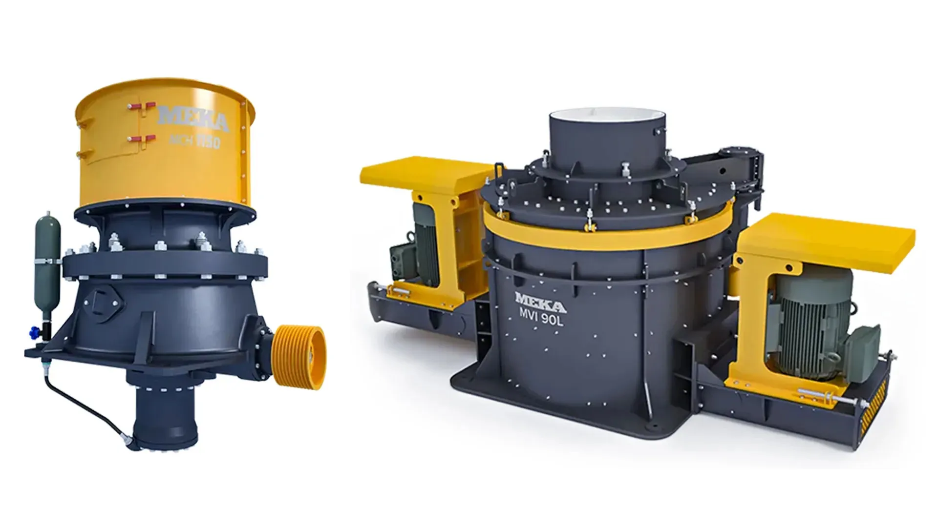
In this article we examine the working principles, structure, main components, and capacity and power calculations of cone crushers and tertiary-type vertical shaft impact crushers — the inseparable secondary–tertiary pairing in aggregate plants that process hard, abrasive volcanic rocks such as basalt, granite and diabase. We explain why these two crushers are deployed together and present examples of plants where they are used. Vertical shaft impact crushers — also known as VSI (Vertical Shaft Impactor) crushers — have become the industry standard for producing cubical aggregate from hard volcanic rocks.
Hydraulic Cone Crushers
Cone crushers are compression crushers.
Figure 1 shows a cross-section of a single-cylinder hydraulic cone crusher (Hydro cone type) and its main components. An eccentric bushing — seated in the bottom shell and driven by a bevel gear set — rotates at a defined gyration speed. The crusher main shaft is mounted eccentrically inside this bushing. At the top, the main shaft is also seated inside the spider bearing located at the top of the upper shell. At the bottom, the main shaft rests on a step bearing which sits on top of the Hydro set piston that is fixed to the lower frame of the crusher. This step bearing carries the axial loads acting on the main shaft. The mantle (movable liner) is mounted on the head, which is keyed to the main shaft. On the inside of the upper shell, a specially shaped concave (fixed liner) is installed.
The hydro set system is essentially a hydraulic cylinder that adjusts the gap between the mantle (movable liner) and the concave (fixed liner) in other words, it controls the product size.

During operation, the mantle approaches and recedes from the concave along the full 360° circumference, applying compressive force to the material. In effect, a cone crusher can be described as a jaw crusher with an infinite number of jaws.
The cone crusher crushing principle is shown in Figure 2.

Rose & English Capacity Formula
Wi: Bond Work Index
D: Bowl diameter
LMAX: Open Side Setting (OSS)
LMIN: Closed Side Setting (CSS)
R: Reduction ratio
K: Statistical factor — K = 0.5 for soft materials such as coal and coke; K = 1 for hard materials such as quartz and granite
ρs: Specific gravity of the crushed material
Rose & English Motor Power Formula
P: Motor power, kW
Wi: Bond Work Index
Q: Capacity, TPH
F80: Feed size at which 80% of the feed material passes, in microns
P80: Product size at which 80% of the crushed material passes, in microns
Cone Crusher Gyration Speed Formula
n: Cone crusher gyration speed, RPM
μ: Coefficient of friction between steel and the crushed material (between 0.2 and 0.3)
d: Maximum product size, cm
α: Angle between the crushing-cone surface and the horizontal
Crushing-Force Calculation

n: Gyration speed, RPM
FB: Crushing force, kN
N: Motor power, kW
x: Distance between cone-generator lines, mm
α: Half of the cone angle
β: Gyration angle
Tertiary Vertical Shaft Impact Crushers
Working Principle of Tertiary VSI Crushers
The rotor in these crushers is enclosed and fully lined with a rock-box pattern. The rotor acts as a high-speed stone pump: it accelerates the material entering it and discharges a high-velocity stream of stone against the crushing-plate group formed by the rock shelf attached to the body — producing rock-on-rock crushing. The velocity of the particles thrown out by the rotor can reach 100 m/s.
In addition to the material that enters the rotor, a controlled amount of feed is also routed around the outside of the rotor (cascade feed). This creates the required material density inside the crushing chamber and improves energy transfer. By controlling this external cascade flow together with variables such as rotor diameter and rotor speed, product gradation, capacity and wear rate are all brought under control.
The crushing principle of tertiary vertical shaft impact crushers is shown in Figure 3.

Main Components of Tertiary VSI Crushers
Figure 4 shows the main components of a tertiary vertical shaft impact crusher. The crusher consists of four main assemblies:
- Crushing-chamber assembly
- Top (roof) assembly
- Main shaft assembly
- Base assembly

The rotor is the “heart” of a tertiary vertical shaft impact crusher. Its job is to impart the kinetic energy — which is then converted into the stress energy required for breakage — to the feed material; in other words, to accelerate it. A distinguishing feature of tertiary VSI rotors is that they are of the enclosed type: the role played by the throw shoes in open rotors is taken here by stone deposits that form inside the rotor itself. The rotor typically has three ports arranged 120° apart. The stone deposits form at the port outlets, on the edge where the material is discharged at high velocity, between the tungsten carbide tips and the trail plates.
Figure 5 shows the rotor of a tertiary VSI and its components; Figure 6 shows a general view of the crushing chamber of a tertiary VSI and its components.


Capacity and Power Analysis of Tertiary VSI Crushers
Analysis Using the Bond Formula
When the Bond formula is used to estimate the specific crushing energy of tertiary VSI crushers, it yields values that differ noticeably from real-world data. As is well known, this formula is built around the work index Wi.
W: Approximate specific energy required for crushing, kWh/t
Wi: Work Index
P: Square-mesh aperture through which 80% of the product (material discharged from the crusher) passes — microns
F: Square-mesh aperture through which 80% of the feed material passes — microns (fines must be screened out of the feed)
N: Required motor power, kW
Q: Capacity, tons/hour
If the product gradation curves of tertiary VSI crushers are examined, the first portion of the curve has a low slope — i.e., the reduction ratio is low in this region.
The slope, and therefore the reduction ratio, increases toward the end of the curve. For this reason, when applying the Bond formula, the value between P35 and P40 should be used in place of P80.
Graph 1 can be used for quick calculations.
Table 1 presents the Work Index and other physical properties of various materials.
| Rock | Rock Type | Wi | ρ (t/m³) | γ (t/m³) | Ai | UCS (MPa) |
|---|---|---|---|---|---|---|
| Andesite | Igneous | 16 ± 2 | 2.6–2.8 | 1.6 | 0.5 | 170–300 |
| Amphibolite | Metamorphic | 16 ± 3 | 2.8–3.0 | 1.7 | 0.2–0.45 | — |
| Sandstone | Sedimentary | 10 ± 3 | 2.7 | 1.6 | 0.1–0.9 | 30–180 |
| Basalt | Igneous | 20 ± 4 | 2.9–3.0 | 1.8 | 0.2 ± 0.1 | 300–400 |
| Limestone | Sedimentary | 12 ± 3 | 2.7 | 1.6 | 0.001–0.03 | 80–180 |
| Coal | Sedimentary | 14 ± 4 | 1.0–1.8 | 0.8 | — | — |
| Clinker | — | — | — | 1.2 | — | — |
| Coke | — | — | — | 0.6 | — | — |
| Diabase | Igneous | 19 ± 4 | 2.8–2.9 | 1.7 | 0.3 ± 0.1 | 250–350 |
| Diorite | Igneous | 19 ± 4 | 2.7–2.8 | 1.6 | 0.4 | 170–300 |
| Dolomite | Sedimentary | 12 ± 3 | 2.7 | 1.6 | 0.01–0.05 | 50–200 |
| Gabbro | Igneous | 20 ± 3 | 2.9–3.0 | 1.8 | 0.4 | 170–300 |
| Gneiss | Metamorphic | 16 ± 4 | 2.7 | 1.6 | 0.5 ± 0.1 | 200–300 |
| Granite | Igneous | 16 ± 6 | 2.7 | 1.6 | 0.55 ± 0.1 | 200–300 |
| Hematite | Sedimentary | — | 5.1 | 2.2–2.4 | 0.35 ± 0.2 | — |
| Magnetite | Sedimentary | — | 5.7 | 2.2–2.4 | 0.50 ± 0.2 | — |
| Marble | Metamorphic | 12 ± 3 | 2.7 | 1.6 | 0.001–0.03 | 80–180 |
| Porphyry | Igneous | 18 | 2.7 | 1.6 | 0.1–0.9 | 180–300 |
| Quartzite | Metamorphic | 16 ± 3 | 2.7 | 1.6 | 0.75 ± 0.1 | 150–300 |
| Syenite | Igneous | 19 ± 4 | 2.7–2.8 | 1.6 | 0.4 | 170–300 |
| Silex (Hornfels) | Metamorphic | 18 ± 3 | 2.8 | 1.65 | 0.7 | 150–300 |
Table 1 — Work Index and other physical properties of various materials. W_i= Bond Work Index (kWh/t); ρ = specific gravity; γ = bulk density; A_i = abrasion index; UCS = uniaxial compressive strength.

Why Use a Cone Crusher as Secondary and a VSI as Tertiary?
Because the cone crusher is a compression crusher, the product taken from it carries internal stress and microcracks. The product is also flaky — flakiness and elongation ratios are not at the level required by the end use. For these reasons it cannot be screened and used directly in concrete and road construction. The product from the cone crusher must be re-crushed in a third stage with an impact-type crusher to relieve its internal stresses and bring it to a cubical shape.
As noted above, cone crushers are effective secondary crushers for hard, abrasive volcanic rocks such as basalt, granite, diabase and river stone. A horizontal shaft impactor is generally not used downstream of a cone in this duty because of high wear rates. Instead, vertical shaft impact crushers — designed around the rock-on-rock crushing principle — are preferred.
Example Plants Using a Cone Crusher (Secondary) and VSI (Tertiary)
1 — 200 TPH Basalt Crushing–Screening Plant for Concrete-Aggregate Production
The plant uses a 1100×900 jaw crusher with a 132 kW motor, a cone crusher equivalent to a Metso HP 300 driven by a 200 kW motor, and a Ø990 mm rotor-diameter VSI crusher driven by 2×250 kW motors.
The plant flow sheet is shown in Figure 7 and the product gradation curve at a 60 m/s rotor tip speed is shown in Graph 2.


2 — Crushing–Screening–Washing Plant for River Material with 0–300 mm Feed Size
This plant crushes river material with a maximum feed size of 300 mm to produce concrete aggregate. Because the material comes from a flowing river it is not heavily contaminated. After natural sand has been separated, a jaw crusher and a cone crusher are used to reduce the rock to a size that the VSI can handle. The plant feed capacity is 300 TPH; after 108 TPH of 0–4 mm natural sand has been removed, 192 TPH of crushed-stone concrete aggregate is produced.
Graph 3 shows the feed gradation of the river material;Figure 8 shows the plant flow sheet; Graph 4 shows the VSI output curve.


Suphi Yavuz
Senior Mechanical Engineer (M.Sc.)
MMO (Chamber of Mechanical Engineers of Turkey) Registration No.: 9219
MEKA GLOBAL