
Crusher Capacity Calculation: Methods for Jaw, Cone and Impact Crushers
Crusher Capacity Calculation: Methods for Jaw, Cone and Impact Crushers
Sizing a crushing-and-screening plant is, at its core, a capacity exercise. Every downstream decision — feeder dimensions, conveyor belt widths, screen deck areas, surge bin volume, and total connected motor power — flows from one set of numbers: how many tonnes per hour each crusher in the circuit can deliver at the closed side setting (CSS) the process actually requires. Get this wrong by even ten percent on a primary jaw crusher, and the secondary stage starves; oversize the tertiary impactor, and you pay for steel and electricity that never converts to product.
The problem is that there is no single "capacity formula" in crushing. Compression-type machines (jaw and cone) follow analytical models grounded in chamber geometry and stroke kinematics — most famously the Rose–English formulation for jaw crushers, which has been the engineering reference since 1956. Impact crushers, by contrast, depend so heavily on rotor peripheral speed, blow-bar geometry, and feed gradation that manufacturers report capacity through empirical tables tied to specific test materials. A plant designer who does not understand the difference will compare two quotations on incompatible bases.
This article walks through the three calculation methods used inside the MEKA crusher portfolio: the analytical Rose–English formula for jaw crushers, the chamber-and-CSS table method for cone crushers, and the empirical capacity-table approach for horizontal-shaft (HSI) and vertical-shaft (VSI) impact crushers. Reduction ratio, nip angle, eccentric stroke, rotor peripheral speed, and the ROR/ROS/SOS chamber configurations are all covered in working detail, with the original handbook tables reproduced below. The objective is a single page on which a process engineer can size a primary, secondary, or tertiary stage without flipping between datasheets.
Crusher Capacity Calculation (Jaw, Cone & Impact)
Why Crusher Capacity Calculation Matters
Plant throughput is governed by the bottleneck stage, not the headline rating of any individual machine. A 600 t/h primary jaw crusher feeding a secondary cone with a true 350 t/h capacity at the required CSS is — for that flowsheet — a 350 t/h plant. Worse, the upstream stockpile fills, the apron feeder cycles intermittently, and intake liners wear unevenly. The first job of capacity calculation is therefore to find the smallest number in the chain at the actual operating CSS, not at the catalogue maximum.
There is also a CAPEX dimension. Crusher prices scale steeply with motor power and rotor mass; a 200 kW cone is meaningfully cheaper than a 315 kW model. Choosing one size larger "to be safe" without running the capacity numbers is one of the most common over-investments in aggregate plant design. Disciplined capacity calculation lets the designer choose the smallest crusher that meets the throughput specification at the fines-end CSS, with a defined margin for liner wear.
The Three Stages of Crushing and Their Capacity Targets
Crushing is conventionally carried out in three stages. Each stage exists because the energy required to break a 1,000 mm boulder down to a 5 mm road-base aggregate in a single machine is mechanically and economically prohibitive. Splitting the duty across stages allows each crusher to operate within its efficient reduction range.
- Primary crushing: the rock or ore from drilling and blasting, with a maximum size of approximately 800–1,500 mm (31.5–59 in), is reduced to below 150–300 mm (6–12 in). Typical machines: jaw crushers (MJ series) and primary impact crushers (MPI series).
- Secondary crushing: the product of the primary stage, with a maximum size of approximately 150–300 mm, is reduced to below 50–80 mm (2–3 in). Typical machines: cone crushers (MCH/MCS series) and secondary impact crushers (MSI/MSIH series).
- Tertiary crushing: the product of the secondary stage, with a maximum size of approximately 50–80 mm, is reduced to below 5–12 mm (0.2–0.5 in). Typical machines: tertiary cone crushers, tertiary impact crushers (MTI series), and vertical-shaft impactors (MVI series) for cubical product shape.

Each downstream stage "sees" only a fraction of the total feed because of by-pass screening and product splits. In Figure 1, a 350 t/h ROM (run-of-mine) feed produces 290 t/h to the primary, 333 t/h to the secondary (after recirculation), and 160 t/h to the tertiary — illustrating why naive throughput addition across stages over-estimates required machine capacity.
Reduction Ratio: The Foundation of Crusher Sizing
What is Reduction Ratio
The reduction ratio (R, also written RR) is the single most important sizing parameter in crushing. It is defined as the ratio of feed size to product size:
REDUCTİON RATİO
R = G / L_MIN
where G is the width of the crushing chamber entrance (m) and L_MIN is the closed side setting, CSS (m). A reduction ratio of 4 means the crusher reduces material to one-quarter of its feed size.
In practice, two definitions are used in the field. The geometric reduction ratio above is calculated from the crusher's nominal feed opening and CSS. A more conservative engineering definition uses the 80 % passing sizes — F80 of feed and P80 of product — giving the so-called F80/P80 reduction ratio, which feeds directly into Bond's third theory of comminution and the work index calculation. For sizing within the catalogued operating range of a crusher, the geometric definition is sufficient.
Typical Reduction Ratios by Crusher Type
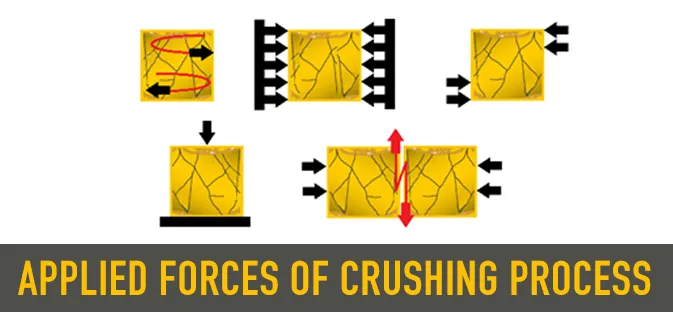
The reduction ratio achievable in a single pass is determined by the crusher's working principle, not by motor power. Compression machines like jaw and cone crushers are limited by chamber geometry and the nip angle that the material can tolerate without slipping; impact machines, where the rock is decelerated against a wall or another rock, can deliver substantially higher single-pass reduction.
| Crusher type | Typical reduction ratio (R) | Working principle |
| Jaw crusher | 2 – 3 | Compression |
| Primary gyratory crusher | 3 – 4 | Compression |
| Cone crusher | 3 – 5 | Compression |
| HSI (Horizontal Shaft Impact) | 7 – 10 | Impact + abrasion |
| VSI (Vertical Shaft Impact) | 4 – 6 | High-velocity impact |
Why Impact Crushers Have the Highest Reduction Ratios
An impact crusher accelerates the feed material on a rotor and projects it against breaker plates (HSI) or against itself (VSI rock-on-rock). The kinetic energy delivered per particle is proportional to the square of the rotor peripheral speed, which is the dominant variable. A 27 m/s rotor — the minimum design value for MEKA HSI machines — delivers roughly four times the specific energy of a typical compression-cycle stroke, and tensile failure planes propagate along natural cleavage rather than only at the contact surfaces. The result is a single-pass reduction of 7 to 10 in soft-to-medium materials, where compression machines need two stages to achieve the same outcome.
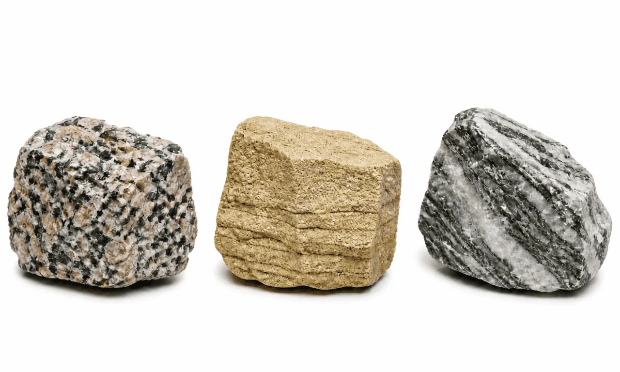
There is a trade-off, however. The same energetic mechanism that gives impact crushers their reduction advantage also drives wear. For materials with SiO₂ content above roughly 12–15 % — basalt, granite, quartzite — chromium-iron blow bars and breaker plates are required, and life-cycle wear-cost economics frequently shift back to cone crushers despite the lower reduction ratio. Material selection criteria are covered in the Mohs Hardness Scale companion article.
Jaw Crusher Capacity Calculation
Jaw crushers are the most extensively analysed crushing machines in the engineering literature. Two design families are produced: single-toggle and double-toggle. Single-toggle jaws are the standard for the aggregate sector because of their simpler kinematics, lower cost, and adequate performance on most rock types. Double-toggle jaws apply pure compression with negligible rubbing motion at the jaw face, which makes them preferred for very hard, abrasive ores such as basalt and quartzite where liner wear must be minimised.
Jaw Crusher Geometry and Critical Parameters
Six geometric and kinematic parameters fully describe a single-toggle jaw crusher for capacity calculation. Each parameter is defined relative to G, the width of the crushing chamber entrance.

- G — width of the crushing chamber entrance (m). Set by the crusher model (e.g., 1,100 mm for MJ 110).
- b — maximum feed size (m). Rule of thumb: b = (0.8 – 0.9) × G. A jaw with G = 1,100 mm accepts a feed of up to ≈ 935 mm.
- L — height of the crushing chamber (m). Approximately L ≈ 2 × G.
- W — length of the crushing chamber (m). Constrained by 1.3 × G < W < 3.0 × G. W appears linearly in the capacity equation, so a longer crusher is a higher-capacity crusher.
- L_MAX (OSS) — open-side setting (m). The chamber gap at the bottom when the toggle is at full extension.
- L_MIN (CSS) — closed-side setting (m). The chamber gap at the bottom when the toggle is at minimum extension. L_MIN sets the product top size.
- L_T — stroke (m). L_T = L_MAX − L_MIN. Typical values: 20–40 mm depending on crusher size.
- n — strokes per minute (rpm). Varies between 100 and 359 rpm depending on crusher size; smaller jaws spin faster.
- θ — nip (grip) angle. The included angle between the fixed and movable jaws, typically 18°–24°. Above ~26°, material slips upward instead of being gripped.
- R — size reduction ratio. R = G / L_MIN. For primary jaws, R is typically 4–6; for secondary jaws, 3–5.
Critical Speed Formula
There is a maximum useful stroke frequency above which a jaw crusher's capacity stops increasing. Beyond the critical speed, the broken material has insufficient time to fall through the chamber gap during the open phase of the cycle, and the machine simply churns the same particles. Critical speed is calculated from the stroke and reduction ratio:
CRİTİCAL SPEED (JAW CRUSHER)
n_C = 47 × [1 / (L_T)^0.5] × [(R − 1) / R]^0.5
n_C = critical strokes per minute (rpm); L_T = stroke (m); R = reduction ratio. Operating speed is typically chosen at 0.85–0.90 × n_C.
In practice, MEKA single-toggle jaw crushers are factory-set in the 250–320 rpm range, comfortably below the critical speed for the design stroke. If a plant operator increases speed via VFD beyond the OEM value, capacity gains saturate quickly and bearing temperatures rise — a common diagnostic when a crusher "feels fast but does not throughput".
The Rose–English Formula for Jaw Crusher Capacity
The Rose–English equation, first published in 1956 and still cited in the standard mineral processing references (Wills, Gupta & Yan), gives capacity at critical speed as a function of stroke, chamber length, CSS, reduction ratio, ore density, and two empirical correction factors:
ROSE–ENGLİSH FORMULA — JAW CRUSHER CAPACİTY
Q_M = 2820 × (L_T)^0.5 × W × (2 × L_MIN + L_T) × [R / (R − 1)]^0.5 × ρ_S × f(P_K) × f(β)
Q_M = capacity (t/h); L_T = stroke (m); W = chamber length (m); L_MIN = CSS (m); R = G / L_MIN; ρ_S = specific gravity of crushed ore (t/m³); f(P_K) = particle-size-distribution correction factor; f(β) = nip-angle correction factor.
What this means in practice: capacity scales with the square root of stroke (so doubling stroke gives a √2 ≈ 1.41× capacity gain), linearly with chamber length W, and roughly linearly with CSS at fixed feed. The reduction-ratio term [R/(R−1)]^0.5 grows slowly as R increases, which is why jaw crushers operating at very high reduction ratios (R > 6) become inefficient compared to a two-stage solution.
The constant 2820 carries units that make the formula dimensionally consistent when SI units are used as specified above. Some published variants of the equation include a chamber-shape constant (typically 1.0 for symmetric chambers) that has been absorbed into the 2820 here, matching the form given in the MEKA Global Handbook.
Particle Size Distribution Factor f(P_K) and Nip Angle Factor f(β)
The two correction factors in the Rose–English formula account for real-world deviations from the idealised geometric model.
PARTİCLE SİZE DİSTRİBUTİON PARAMETER
P_K = (d_MAX − d_MIN) / d_MEAN
d_MAX = maximum feed particle size; d_MIN = minimum feed particle size; d_MEAN = mean feed particle size. P_K is dimensionless and characterises the spread of the feed gradation.
f(P_K) is read from the empirical curve below. For tightly graded feeds (P_K < 0.4) the factor is approximately 0.40, indicating that uniform feed gradation reduces capacity because particles do not nest efficiently in the chamber. As feed becomes more poorly graded (P_K > 0.8), f(P_K) approaches 0.85–0.90 — well-distributed feeds fill the chamber more completely and yield higher throughput.
f(β) corrects for nip angle. At the design nip angle (β ≈ 0.4–0.5 rad / 23–29°) the factor is unity. Above β ≈ 0.7 rad (40°), f(β) rises sharply because the formulation accounts for re-circulation of slipping material — this is a region where real crushers do not operate, and the curve is included primarily as a design boundary.
 versus particle size distribution parameter. Right: f(β) versus nip angle (radians). Source: MEKA Global Handbook, p. 36.")
Worked Example — Calculating Capacity for an MJ 110 at 125 mm CSS
Consider a MEKA MJ 110 single-toggle jaw crusher operating in primary duty at a CSS of 125 mm with quarried limestone of specific gravity 2.7 t/m³. Catalogue dimensions: G = 1,100 mm, W = 850 mm. Assume a stroke L_T = 30 mm, well-graded blasted feed (P_K ≈ 0.9, f(P_K) ≈ 0.88), and a design nip angle (f(β) ≈ 1.0).
- Step 1 — Reduction ratio: R = G / L_MIN = 1.100 / 0.125 = 8.8.
- Step 2 — [R/(R−1)]^0.5: = (8.8 / 7.8)^0.5 = 1.061.
- Step 3 — (L_T)^0.5: = (0.030)^0.5 = 0.1732 m^0.5.
- Step 4 — (2 × L_MIN + L_T): = (2 × 0.125 + 0.030) = 0.280 m.
- Step 5 — Apply Rose–English: Q_M = 2820 × 0.1732 × 0.85 × 0.280 × 1.061 × 2.7 × 0.88 × 1.0 ≈ 295 t/h.
Cross-check against the MEKA capacity table for the MJ 110 (Table 3 below): at 125 mm jaw opening, the catalogued range is 140–175 t/h. The discrepancy is a useful illustration of why catalogue figures use conservative correction factors. The catalogue assumes a typical, not optimum, feed gradation, and incorporates a recirculation allowance for tramp oversize material that bypasses the crusher chamber on the first pass. For plant design, always use the manufacturer's tabulated capacity at the planned CSS, and reserve the analytical Rose–English calculation for sensitivity analysis around the design point.
MEKA Jaw Crusher Capacity Tables
The general technical specifications for the MEKA MJ (primary) and MJS (secondary) series are reproduced below.
| Model | Opening (mm) | CSS min–max (mm) | Capacity (t/h) | Power (kW) | Weight (kg) |
| MJ 60 | 610 × 380 | 40 – 150 | 20 – 80 | 30 | 6,000 |
| MJ 65 | 650 × 500 | 40 – 150 | 25 – 100 | 45 | 7,000 |
| MJ 70 | 700 × 400 | 30 – 100 | 25 – 110 | 45 | 4,200 |
| MJ 90 | 900 × 650 | 60 – 150 | 50 – 200 | 75 | 11,400 |
| MJ 110 | 1100 × 850 | 100 – 200 | 100 – 300 | 132 | 33,000 |
| MJ 130 | 1300 × 1000 | 125 – 250 | 275 – 600 | 160 | 43,000 |
| MJ 110C | 1070 × 770 | 75 – 210 | 135 – 340 | 110 | 19,000 |
| MJ 120C | 1200 × 870 | 70 – 175 | 175 – 595 | 160 | 27,990 |
| MJ 150C | 1400 × 1200 | 125 – 250 | 340 – 970 | 200 | 50,950 |
| MJS 90 | 900 × 200 | 25 – 75 | 10 – 80 | 30 | 6,000 |
| MJS 110 | 1100 × 350 | 25 – 100 | 40 – 200 | 75 | 11,000 |
. Source: MEKA Global Handbook, p. 38.")
Cone Crusher Capacity Calculation
Cone crushers occupy the secondary and tertiary positions in most aggregate flowsheets. They are particularly suited to volcanic and metamorphic rocks with high SiO₂ content — basalt, granite, quartzite — where the rolling, cyclical compression between mantle and concave produces a more cubical product than would be obtained with a jaw crusher in the same duty. MEKA produces three primary cone models: MCS 900 (spring), MCH 900 (hydraulic), and MCH 1150.
Cone Crusher Capacity Variables
Cone crusher capacity is dominated by four variables: closed side setting (CSS), eccentric stroke, crushing chamber type (concave profile), and motor power. CSS sets the top size of the product; eccentric stroke determines the volume swept per gyration; chamber type — Extra Coarse (EC), Coarse (C), Medium Coarse (MC), Medium (M), or Medium Fine (MF) — sets the maximum acceptable feed size and the degree of inter-particle compression; motor power caps the available crushing force at the operating gyration speed.
Although the Rose–English formulation can be extended to cone crushers (as Q = {[W_i × D × ρ_S × (L_MAX + L_MIN)^0.5] / [2 × (R / (R−1))^0.5]} × (L_MAX + L_MIN) × K, where W_i is the Bond Work Index, D the bowl diameter, and K an empirical statistical factor — 0.5 for soft materials such as coal, 1.0 for hard materials such as quartz and granite), the formula is rarely used in plant design. The chamber profile alone produces capacity differences of 30–40 % between EC and MF configurations on the same machine, and these differences are not captured analytically. Industry practice is therefore to size cone crushers from the manufacturer's chamber-and-CSS table.
Capacity Tables by Model and CSS
MEKA MCH 900 capacity values, by chamber type, eccentric stroke, and CSS, are reproduced in Table 3. All values assume a feed bulk density of 1.6 t/m³.
| Chamber | Max feed (mm) | ECC stroke (mm) | Motor (kW) | 13 mm CSS | 16 mm CSS | 19 mm | 22 mm | 25 mm | 29 mm | 32 mm | 35 mm |
| EC | 130 | 16 | 75 | — | — | 85 | 90 | 95 | 100 | 105 | 110 |
| EC | 130 | 19 | 90 | — | — | 100 | 110 | 115 | 120 | 125 | 130 |
| EC | 130 | 22 | 90 | — | — | — | — | 135 | 140 | 145 | 150 |
| EC | 130 | 25 | 110 | — | — | — | — | — | 155 | 160 | 165 |
| EC | 130 | 29 | 110 | — | — | — | — | — | — | 180 | 185 |
| C | 110 | 16 | 75 | — | 80 | 85 | 85 | 90 | 95 | 100 | — |
| C | 110 | 19 | 90 | — | — | 95 | 100 | 105 | 110 | 115 | 120 |
| C | 110 | 22 | 90 | — | — | — | — | 125 | 130 | 135 | 140 |
| C | 110 | 25 | 110 | — | — | — | — | — | 140 | 145 | 150 |
| C | 110 | 29 | 110 | — | — | — | — | — | — | 180 | 165 |
| MC | 85 | 16 | 55 | 60 | 70 | 75 | 80 | 85 | — | — | — |
| MC | 85 | 19 | 75 | 70 | 80 | 85 | 90 | 100 | 105 | — | — |
| MC | 85 | 22 | 75 | — | — | 90 | 100 | 110 | 125 | — | — |
| MC | 85 | 25 | 90 | — | — | 100 | 106 | 115 | 135 | — | — |
| MC | 85 | 29 | 110 | — | — | — | 110 | 115 | 125 | — | — |
| MC | 85 | 32 | 110 | — | — | — | — | — | 135 | — | — |
| Model | Chamber | Max feed (mm) | 38 mm CSS | 42 mm | 46 mm | 50 mm | 55 mm |
| MCS 900 | EC | 240 | — | — | — | 175 | 195 |
| MCS 900 | C | 200 | — | — | 155 | 165 | — |
| MCS 900 | M | 160 | 120 | 150 | — | — | — |
| Chamber | Max feed (mm) | 13 mm | 16 mm | 19 mm | 22 mm | 25 mm | 29 mm | 32 mm | 35 mm | 38 mm | 41 mm | 44 mm |
| EC | 215 | — | — | 80–190 | 90–260 | 95–280 | 100–290 | 110–310 | 120–340 | 130–340 | 135–350 | 140–320 |
| C | 175 | — | 70–120 | 80–230 | 90–260 | 100–280 | 110–300 | 120–320 | 125–340 | 130–300 | 140–280 | 150–220 |
| MC | 140 | — | 75–175 | 80–250 | 85–260 | 90–280 | 95–320 | 110–340 | 120–300 | 130–280 | 140–220 | 150–190 |
| MF | 85 | 50–120 | 55–200 | 60–210 | 65–220 | 70–235 | 75–250 | 105–240 | 110–230 | 120–180 | 125–160 | — |
How CSS (Closed Side Setting) Determines Throughput
Reading down any column of Table 3 reveals the dominant pattern in cone crusher behaviour: for a fixed chamber, capacity grows roughly linearly with CSS. The MCH 900 EC at 25 mm eccentric stroke delivers 110 t/h at 25 mm CSS but 165 t/h at 35 mm CSS — a 50 % capacity gain for a 10 mm CSS increase. The trade-off is product gradation: a 35 mm CSS produces a coarser P80 than 25 mm, which may exceed downstream screen aperture sizes and force recirculation.
CSS selection is therefore an iterative balance: choose the largest CSS that still produces a P80 below the target aperture, then check that the resulting throughput meets the plant specification. If it does not, the next move is either to a larger eccentric stroke (gaining ~10–15 % capacity per stroke step at fixed CSS) or to a coarser chamber profile.
Choosing Between MCS (Spring) and MCH (Hydraulic) Cone Crushers
The MCS 900 (spring-relief) and MCH 900 (hydraulic-relief) share the 900 mm head class but differ substantially in operational characteristics:
- MCS 900 — spring-release: 60–214 t/h, 110 kW, max feed 160–240 mm, CSS 22–38 mm. Mechanically simple; recommended for secondary duty on softer materials and applications with limited tramp metal exposure. CSS adjustment is manual.
- MCH 900 — hydraulic-release: 60–165 t/h, 110 kW, max feed 85–130 mm, CSS 13–35 mm. Hydroset cylinder allows on-the-fly CSS adjustment, automated tramp-iron release, and continuous wear compensation. Recommended for tertiary duty and any application where uncrushable material exposure is non-negligible.
- MCH 1150: 80–340 t/h, 200 kW, max feed 80–210 mm, CSS 13–44 mm. The high-capacity hydraulic option for medium-to-large aggregate plants.
MEKA's automation system continuously monitors mantle and concave wear and maintains the CSS setpoint by adjusting hydroset pressure as liners erode. When tramp iron enters the chamber, the relief valve opens, the bowl rises, and the foreign material clears without operator intervention or driveline shock load. This is the principal economic advantage of hydraulic release in continuous-operation plants.
Impact Crusher Capacity Calculation (HSI and VSI)
Impact crushers — both horizontal-shaft (HSI) and vertical-shaft (VSI) — break rock through high-velocity collisions rather than slow compression. The dominant capacity variable is rotor peripheral speed, with chamber geometry, blow-bar profile, and rotor mass as secondary factors. Because rock fragmentation under impact is statistical rather than deterministic, no single closed-form capacity equation has gained general acceptance, and OEM capacity tables grounded in standardised reference materials are the working basis for plant design.
HSI (Horizontal Shaft Impact) — Capacity by Rotor Size
MEKA's HSI portfolio splits across primary (MPI series, up to 1,000–1,200 mm feed), secondary (MSI series, up to 500–600 mm feed), tertiary (MTI series, up to 90–150 mm feed), and the heavy-duty MSIH series for hard, abrasive secondary duty. All HSI capacities below assume a bulk density of 1.6 t/m³ and exclude motor group, support legs, and maintenance platform from quoted weights.
| Specification | MPI 1111 | MPI 1114 | MPI 1313 | MPI 1515 | MPI 1620 |
| Rotor diameter × length (mm) | 1100 × 1070 | 1100 × 1400 | 1300 × 1300 | 1500 × 1500 | 1600 × 2000 |
| Feed opening (mm × mm) | 1110 × 924 | 1000 × 1400 | 1320 × 1200 | 1540 × 1360 | 2040 × 1630 |
| Maximum feed size (mm) | 600 | 600 | 900 | 1000 | 1300 |
| Motor power (kW) | 160 | 200 | 250 | 315 | 500 |
| Capacity (t/h) | 150 – 200 | 250 – 350 | 300 – 500 | 400 – 600 | 600 – 950 |
| Weight (kg) | 15,100 | 16,800 | 22,400 | 26,800 | 40,500 |
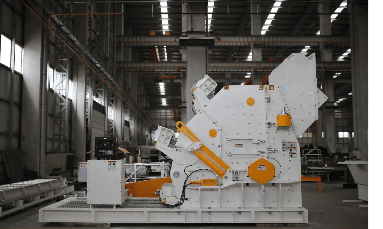
| Specification | MSI 1210 | MSI 1312 | MSI 1315 |
| Rotor (mm) | 1150 × 1000 | 1300 × 1250 | 1300 × 1500 |
| Feed opening (mm) | 1080 × 825 | 1310 × 800 | 1510 × 800 |
| Max feed (mm) | 250 | 350 | 350 |
| Motor (kW) | 132 – 160 | 200 | 250 – 315 |
| Capacity (t/h) | 100 – 150 | 150 – 250 | 250 – 350 |
| Weight (kg) | 12,400 | 18,000 | 22,600 |
| Specification | MS 1110H | MS 1112H | MS 1115H | MS 1415H | MS 1420H |
| Rotor (mm) | 1120 × 1000 | 1120 × 1200 | 1120 × 1500 | 1400 × 1500 | 1400 × 2000 |
| Feed opening (mm) | 1040 × 550 | 1320 × 550 | 1560 × 550 | 1530 × 1000 | 2030 × 1000 |
| Max feed (mm) | 300 | 300 | 300 | 350 | 350 |
| Motor (kW) | 160 | 200 | 250 – 315 | 400 | 500 |
| Capacity (t/h) | 130 – 200 | 170 – 250 | 250 – 350 | 350 – 450 | 380 – 600 |
| Weight (kg) | 12,280 | 14,320 | 18,800 | 28,760 | 35,000 |
| Specification | MT 1105 | MT 1110 | MT 1115 | MT 130 | MT 1314 |
| Rotor (mm) | 1100 × 500 | 1100 × 1000 | 1100 × 1500 | 1286 × 655 | 1286 × 1355 |
| Feed opening (mm) | 520 × 310 | 1020 × 310 | 1520 × 310 | 1040 × 550 | 1390 × 210 |
| Max feed (mm) | 150 | 150 | 150 | 90 | 90 |
| Motor (kW) | 110 | 200 – 250 | 315 | 90 – 132 | 160 – 250 |
| Capacity (t/h) | 100 – 120 | 220 – 250 | 280 – 320 | 100 – 120 | 220 – 250 |
| Weight (kg) | 8,750 | 14,000 | 17,470 | 8,400 | 13,480 |
Rotor Peripheral Speed Effect on Capacity
MEKA HSI machines are designed around a minimum rotor peripheral speed of 27 m/s. Below this threshold, the kinetic energy of impact is insufficient to fragment medium-hard rock at the design capacity. The relationship between peripheral speed (v_p), rotor diameter (D), and rotational speed (n) is straightforward:
ROTOR PERİPHERAL SPEED
v_p = π × D × n / 60
v_p in m/s; D in m; n in rpm. For an MPI 1313 with D = 1.30 m running at 600 rpm, v_p = 40.8 m/s.
Increasing peripheral speed shifts the product gradation finer and raises the reduction ratio, but also accelerates blow-bar wear at a roughly cubic rate with speed. For a given rotor, doubling speed approximately doubles capacity (because more impacts occur per unit time) but increases wear cost per tonne by a factor of 6–8. The optimum operating speed is therefore material-dependent: harder feeds run at the lower end (27–35 m/s); softer limestone runs comfortably at 50–55 m/s with acceptable wear economics.
VSI (Vertical Shaft Impact) — Rock-on-Rock vs Rock-on-Steel Configurations
Vertical shaft impact crushers occupy the tertiary and quaternary positions, where their job is to produce highly cubical aggregate and to eliminate soft particles by selective fragmentation. Three chamber configurations are used:
- ROR (Rock-on-Rock) — closed rotor, stone box: feed is accelerated by the rotor and projected against a layer of pre-deposited rock (the "stone box"). Wear is minimised because rock breaks against rock; this is the standard configuration for abrasive materials such as basalt, granite, and river gravel.
- ROS (Rock-on-Steel) — closed rotor, anvil ring: feed is projected against high-chrome anvils. Higher reduction ratio and finer product than ROR, but anvil wear is significant. Suitable for limestone and dolomite.
- SOS (Steel-on-Steel) — open rotor, anvil ring: the feed is accelerated by steel-tipped rotor surfaces and projected against anvils. Maximum reduction ratio but maximum wear; reserved for soft feeds where product cubicity dominates the economics.
Final product gradation depends strongly on rotor peripheral speed. For basalt and river stone in ROR mode, MEKA design values are 56 m/s; for limestone and dolomite, 70 m/s. ROS mode operates at 41 m/s and 56 m/s for soft and medium-hard feeds respectively.
| Crusher model | Max feed (mm) | Capacity (t/h) | Motor (kW) | Weight (kg) |
| M 90L (ROR SD) | 50 | 200 | 200 – 250 | 10,160 – 10,525 |
| M 90L (ROR DD) | 50 | 300 | 2 × 110 – 160 | 11,730 – 11,930 |
| M 90L (ROS SD) | 50 | 250 | 200 – 250 | 12,000 – 12,370 |
| M 90L (ROS DD) | 50 | 300 | 2 × 110 – 160 | 13,580 – 13,775 |
| M 90L (SOS SD) | 75 | 250 | 200 – 250 | 12,500 – 12,865 |
| M 90L (SOS DD) | 75 | 400 | 2 × 200 | 15,095 |
| M 90G (ROR SD) | 50 | 200 | 200 – 250 | 9,180 – 9,540 |
| M 90G (ROR DD) | 50 | 300 | 2 × 110 – 200 | 11,090 – 11,550 |
| M 90G (ROS SD) | 50 | 200 | 200 – 250 | 11,660 – 12,060 |
| M 90G (ROS DD) | 50 | 300 | 2 × 110 – 200 | 13,240 – 14,060 |
| M 70G (ROR SD) | 35 | 120 | 110 – 160 | 5,595 – 5,695 |
| M 70G (ROR DD) | 35 | 160 | 2 × 110 | 7,100 |
| M 70G (ROS SD) | 35 | 120 | 110 – 160 | 7,020 – 7,120 |
| M 70G (ROS DD) | 35 | 160 | 2 × 110 | 8,525 |
Why Impact Crusher Sizing Differs from Compression Crushers
Three reasons explain why impact crusher capacity is reported via tables rather than analytical formulas. First, fragmentation under impact loading depends on the local stress wave dynamics inside each particle, which is a function of rock texture (grain size, microcrack density) that varies between deposits even within the same lithology. Second, rotor-feed interaction is statistical: not every particle is struck on the optimum face of a blow bar, and the distribution of impact angles cannot be reduced to a single closed-form term. Third, blow-bar wear continuously changes the effective rotor geometry over a maintenance cycle — a fresh chrome bar produces different gradation than one at 60 % wear, even at identical rotor speed.
Practical consequence: when comparing impact crusher quotations, always demand the test material specification against which the capacity figure is given. A vendor capacity quoted on "limestone" can be 30–40 % higher than the same machine on basalt at the same CSS, and an unqualified comparison between two manufacturers' headline numbers is meaningless without that footnote.
Comparing the Three Calculation Methods Side-by-Side
The three calculation methods reflect three fundamentally different fracture mechanisms and three different industrial conventions. Table 11 summarises the differences for plant-design reference.
| Method | Crusher type | Primary inputs | Output basis | Sensitivity |
| Analytical (Rose–English) | Jaw, Cone (extended) | Geometry G/W/L_T, R, ρ_S, f(P_K), f(β) | Closed-form Q in t/h | Sensitive to feed gradation; ±20% vs catalogue |
| Chamber-and-CSS table | Cone (MCH/MCS) | Chamber type, eccentric stroke, CSS | Tabulated Q at 1.6 t/m³ | Sensitive to chamber wear; ±10% over liner life |
| Empirical capacity table | HSI (MPI/MSI/MSIH/MTI), VSI | Rotor size, feed size, rotor speed | Tabulated Q range | Sensitive to material; ±30% basalt vs limestone |
Decision Matrix: When to Use Which Crusher
Crusher selection is a multi-variable decision. The matrix below condenses the principal selection criteria for the three primary stages.
| Criterion | Jaw (MJ) | Cone (MCH/MCS) | HSI Primary (MPI) | HSI Secondary (MSI/MSIH) | VSI (MVI) |
| Stage | Primary | Secondary, Tertiary | Primary | Secondary | Tertiary, Quaternary |
| Max feed size | 1,200 mm | 240 mm | 1,300 mm | 350 mm | 75 mm |
| Reduction ratio | 2 – 3 | 3 – 5 | 7 – 10 | 7 – 10 | 4 – 6 |
| Best material hardness | Hard, abrasive | Hard, abrasive | Soft to medium | Medium | Soft to medium |
| Mohs limit (recommended) | ≤ 7 | ≤ 7 | ≤ 5 | ≤ 6 (MSIH ≤ 7) | ≤ 7 |
| SiO₂ content tolerance | Any | Any (high preferred) | < 12 % | < 15 % (MSIH < 25 %) | Any (ROR) |
| Product shape | Slabby | Cubical | Cubical | Cubical | Highly cubical |
| Typical capacity range | 20 – 970 t/h | 60 – 340 t/h | 150 – 950 t/h | 100 – 600 t/h | 120 – 400 t/h |
Frequently Asked Questions
1. How is crusher capacity calculated?
It depends on the crusher type. For jaw crushers, the Rose–English formula relates capacity to chamber geometry (stroke, CSS, chamber length), reduction ratio, ore density, and two correction factors for feed gradation and nip angle. For cone crushers, capacity is read from manufacturer tables organised by chamber type, eccentric stroke, and CSS at a reference bulk density of 1.6 t/m³. For impact crushers (HSI and VSI), capacity is provided as an empirical range at standardised test material conditions, with rotor size and rotor peripheral speed as the dominant variables.
2. What is the Rose–English formula?
The Rose–English formula, introduced in 1956, calculates jaw crusher capacity at critical speed as Q_M = 2820 × (L_T)^0.5 × W × (2 × L_MIN + L_T) × [R / (R−1)]^0.5 × ρ_S × f(P_K) × f(β). It is the foundational analytical model for compression crushing and remains the reference equation in the standard mineral processing texts. The formula incorporates all six primary geometric parameters of a single-toggle jaw crusher and two empirical correction factors for feed gradation (P_K) and nip angle (β).
3. What is reduction ratio in crushers?
Reduction ratio R = G / L_MIN is the ratio of feed size (chamber entrance width G) to product size (closed side setting L_MIN). It quantifies how much size reduction one crusher achieves in a single pass. Typical ranges: jaw crusher 2–3, primary gyratory 3–4, cone crusher 3–5, HSI 7–10, VSI 4–6. Impact crushers achieve higher reduction ratios because high-velocity impact propagates fracture along internal flaw planes more effectively than slow compression.
4. What CSS should I use for my cone crusher?
Choose the largest CSS that produces a P80 below the target downstream screen aperture, then verify that the resulting capacity meets the plant throughput specification. For a target product top size of, say, 25 mm, set the cone CSS in the 19–22 mm range (depending on the steepness of the gradation curve for the chamber type). A larger CSS gives roughly linear capacity gain at the cost of coarser product; a smaller CSS produces finer product but reduces throughput. Refer to Tables 3, 4, and 5 above for MCH 900, MCS 900, and MCH 1150 capacity at each CSS step.
5. Why doesn't impact crusher capacity have a closed-form formula like a jaw?
Impact fragmentation is statistical, not deterministic. A particle struck by a blow bar fragments along internal microcracks whose density and orientation vary between deposits. Rotor–feed interaction is not deterministic either: not every particle hits the optimum face of a blow bar, and the impact-angle distribution cannot be reduced to a single analytical term. Rotor peripheral speed, rotor diameter, and feed gradation interact non-linearly, and blow-bar wear continuously changes effective rotor geometry. Manufacturers therefore provide capacity tables grounded in standardised test materials at reference rotor speeds (e.g., 27 m/s minimum, 53 m/s for tertiary, 56–70 m/s for VSI).
6. How does material hardness affect crusher capacity?
Hardness influences capacity through the Bond Work Index W_i, which appears explicitly in the cone-crusher power equation P = W_i × Q × [1 − (P80 / F80)^0.5] × (100 / P80)^0.5 and implicitly in the empirical capacity tables for impact crushers. Higher W_i (hard rock) requires more specific energy per tonne crushed, which means lower capacity at the same motor power, or the need for a larger motor. Practical capacity penalty: roughly 25–30 % reduction in t/h when moving from limestone (W_i ≈ 11 kWh/t) to granite (W_i ≈ 16 kWh/t) on the same machine. See the companion article on rock physical properties for typical W_i values.
7. Can I use the same Rose–English formula for primary and secondary jaw crushers?
Yes — the formula structure is identical. What changes between primary and secondary duty is the input values: G is smaller for secondary (e.g., MJS 110 has a 1,100 × 350 mm opening versus MJ 110's 1,100 × 850 mm), L_MIN is finer (25–100 mm for MJS series versus 100–200 mm for MJ 110), and the resulting reduction ratio differs accordingly. The empirical correction factors f(P_K) and f(β) also differ because the secondary feed is the (more-uniform) product of the primary stage.
8. What is the typical capacity of a primary jaw crusher?
MEKA primary jaw crushers cover a range from 20 t/h (MJ 60, 610 × 380 mm opening) to 970 t/h (MJ 150C, 1,400 × 1,200 mm opening) at the upper end of CSS. The MJ 110 (1,100 × 850 mm) — a typical mid-range primary for aggregate plants — is rated at 100–300 t/h depending on CSS. For mining duties with feed in the 1–1.5 m range, the MJ 130 (1,300 × 1,000 mm) at 275–600 t/h is the standard reference point. Always cross-check the catalogue capacity at the planned CSS, not at the maximum CSS, and apply a 10–15 % derating for liner wear over the maintenance cycle.
Related MEKA Resources
Each crusher discussed in this article has a dedicated product page in the MEKA Global catalogue with model-specific datasheets, dimensional drawings, and application photography:
- MEKA jaw crusher product line
- Cone crusher models — MCH and MCS series
- Primary impact crusher (MPI series)
- Secondary impact crusher (MSI / MSIH series)
- Tertiary impact crusher (MTI series)
- VSI crusher (MVI series)
- Hammer crusher (MH series)
- Belt Conveyor Capacity Calculation (downstream sizing for crusher discharge)
- Physical Properties of Rocks (Bond Work Index W_i reference values)
- Mohs Hardness Scale (crusher selection by rock hardness)
MEKA GLOBAL