What Is a Tertiary Impact Crusher and How Does It Work?
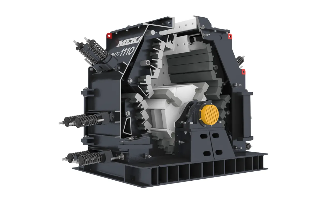
Tertiary impact crushers carry out the final crushing stage in crushing-and-screening plants, making it possible to obtain the final size in aggregate production. In this article, focusing on horizontal-shaft tertiary crushers, we examine their working principles, advantages and technical details.
What Are Tertiary Impact Crushers?
Tertiary crushers are generally designed to crush the oversize of the material crushed and screened in the secondary crushers, and the excess, undesirable material from the product ranges. Tertiary impact crushers used in crushing-and-screening plants are divided into two groups: horizontal-shaft tertiary impact crushers and vertical-shaft tertiary impact crushers. Especially in the mining sector, in plants processing hard and abrasive ores where cone crushers are used as secondary crushers, the tertiary impact crushers are mostly vertical-shaft crushers. In the aggregate sector, in plants where horizontal-shaft impact crushers are used as secondary crushers, the tertiary impact crushers are mostly horizontal-shaft impact crushers. In plants processing basalt, granite and similar volcanic rocks where cone crushers are used as secondary crushers, vertical-shaft tertiary impact crushers are used, as in the mining sector.
These differences make it possible to select the correct solution according to the crusher's application area and the desired product size.

The Advantages and Areas of Use of Tertiary Horizontal-Shaft Impact Crushers
Horizontal-shaft tertiary impact crushers are preferred especially in the aggregate and mining sectors. Below you can find the main advantages specific to these crushers.
The most important advantages of horizontal-shaft tertiary impact crushers are as follows.
- The maximum material size they can crush is greater than that of vertical-shaft impact crushers. In some crushers it can go up to 200 mm.
- In recent years, developments in the metallurgy sector have made it possible to use horizontal-shaft tertiary impact crushers for abrasive river material and volcanic rocks in addition to non-abrasive materials. However, today vertical-shaft tertiary crushers are used more for volcanic rocks.
- The fully symmetric rotor and crushing chamber design allows the crusher to operate in both directions. The fully openable wide doors on both sides of the crusher provide very easy maintenance access, thus considerably shortening maintenance times.
- In the majority of these crushers, there are two crushing plates on each of the two sides within the crushing area. The upper plate is called the crushing plate and the lower plate the grinding plate. The liners, which can be easily mounted on these plates, are designed according to the crushing or grinding purpose. The gap between the crusher's crushing and grinding plates and the rotor can be easily adjusted fully hydraulically, and a stable product distribution is obtained throughout the operating time.
- The product obtained from the crusher has a crack-free, sound, cubical-shaped structure and is very suitable for concrete and road construction.
The Structure and Main Components of the Tertiary Horizontal-Shaft Impact Crusher
The efficient operation of the horizontal-shaft tertiary impact crusher depends on every component — from the rotor design to the crushing plates — working in harmony. In this section, the structural elements of the crusher will be explained step by step.
Since the sizes of the material fed into tertiary impact crushers are smaller than those of primary and secondary impact crushers, and the crusher capacity is also lower than that of primary and secondary impact crushers, the crushing areas of these crushers are smaller; consequently, their rotor diameters and widths, rotor moments of inertia, crushing-plate widths and body dimensions are smaller. In Figure 2 we see the technical specifications of tertiary impact crushers with a rotor diameter of Ø1000 mm and the main components of the bearing system.

| PART NO. | PART NAME | TDK 10/05/4 | TDK 10/10/4 | TDK 10/15/4 |
|---|---|---|---|---|
| 1 | DISC GROUP | Disc thickness: 70 Number of discs: 3 |
Disc thickness: 70 Number of discs: 4 |
Disc thickness: 70 Number of discs: 6 |
| 2 | BLOW BAR | Bar size: 75*305*500 Number of bars: 1*4 |
Bar size: 75*305*500 Number of bars: 2*4 |
Bar size: 75*305*500 Number of bars: 3*4 |
| 3 | SHAFT | Shaft material: SAE 4340 Shaft diameter: at bearing Ø140 In the middle: Ø160 |
Shaft material: SAE 4340 Shaft diameter: at bearing Ø160 In the middle: Ø180 |
Shaft material: SAE 4340 Shaft diameter: at bearing Ø200 In the middle: Ø220 |
| 4 | RINGFEDER | 160*210*52 Rfn 7012 | 180*235*60 Rfn 7012 | 220*285*74 Rfn 7012 |
| 5 | BEARING | 22332 CCK/W33+H2332 | 23236 CCK/W33+H2336 | 23244 CCK/W33 +H2344 |
| 6 | BEARING HOUSING | SNL 3140 | SNL 3236 | SNL 3244 |
| 7 | CLAMPING RING | 2 FRB 9/340 | 2 FRB 6/320 | 2 FRB 10/400 |
| 8 | DRIVE PULLEY | Ø800 * 10 SPC belts | Ø800 * 10 SPC belts | Ø800 * 10 SPC belts |
| 9 | RINGFEDER | 130*180*52 Rfn 7012 | 150*200*52 Rfn 7012 | 170*225*60 Rfn 7012 |
| 10 | CONNECTION BOLT | M 20 | M 20 | M 24 |
| ROTOR SIZE | ∅1000*500 | ∅1000*1000 | ∅1000*1500 | |
| MOTOR POWER kW | 90-160 KW | 160-250 KW | 200-315 KW | |
| FEED OPENING SIZE | 280*500 mm | 280*1000 mm | 280*1500 mm | |
| MAXIMUM FEED SIZE | 150 mm | 150 mm | 150 mm | |
| ROTOR PERIPHERAL SPEED m/s | 30-60 | 30-60 | 30-60 | |
| CAPACITY TPH | 70-100 | 130-170 | 170-250 | |
| TOTAL CRUSHER WEIGHT | ~9000 KG | ~12500 KG | ~19000 KG |
Tertiary Horizontal-Shaft Impact Crusher Rotor
In tertiary crushers, the rotor is the main component where the rotational moment and impact energy combine. In MEKA's engineering designs, the rotor geometry has been developed to optimize the material flow so as to increase both the crushing efficiency and the blow-bar life.
Rotor Design and Material Selection
Although different companies have different designs for the tertiary impact crusher rotor, as in secondary impact crushers there is a shaft sleeve made of casting or thick-walled pipe. The rotor discs are made either of hot-rolled steel of St 37-2 (S 235JR) grade, or of cast steel of GS 38 or GS 45 grade. The disc thicknesses are around 60–75 mm and are welded either from steel drawn pipe with a wall thickness of 25–40 mm, or from a cast-steel shaft sleeve (DN 250 SCH 160 or equivalent); alternatively, thick-walled pipe is welded in sections between the discs (with appropriate weld preparations). After the welding process, stress-relief annealing is applied. Depending on the crusher size, the number of discs varies between 2 and 6.
Blow-Bar Mounting and Wear Resistance
Just as blow-bar seating pieces are welded to the parts where the blow bars pass, in some designs the tops of the discs are completely covered with removable, wear-resistant cast disc-protection pieces connected by a pinned system.

In horizontal-shaft tertiary impact crushers, since the crushing area is small, the discs come into contact with the material more than in secondary and primary impact crushers. For this reason, two methods are followed. The most effective method is to use disc-protection pieces cast from Hadfield steel, connected to the discs by a pinned or bolted method.
After the blow bars are seated by sliding them in from the side into their slots in the disc group, to prevent their axial movement, approximately 20 mm-thick connection pieces fix them in place. These pieces are fastened with M12 bolts to the recesses on the outer faces of the discs at the two ends and to the corresponding recesses in the blow bars.Figure 4 shows this connection method.

Tertiary horizontal-shaft impact crusher rotor diameters are generally chosen around Ø1000 mm – Ø1300 mm, and rotor widths around 500, 1000, 1500 and 2000 mm. If the material to be crushed is limestone or similar low-abrasive material, the blow bars are made of Hadfield steel (EN 10349 austenitic manganese cast steel). If the material to be crushed is abrasive, they are made of high-chromium white cast iron (ASTM A532, BS EN 12513, DIN 1695) or of ceramic-reinforced MMC material.
In horizontal-shaft tertiary impact crushers too, as in primary and secondary horizontal-shaft impact crushers, a forged-steel main shaft of SAE 4340 grade is used. The main shaft is connected to the disc group by conical clamping rings (RINGFEDER). In the bearing system, heavy-duty, C3-clearance SKF or equivalent brand double-row spherical roller bearings are used. As bearing housings, SKF SNL-type or equivalent bearing housings are used.
The drive pulley is also connected to the main shaft with standard conical clamping rings. The drive pulley diameter is generally around 800 mm, and the rotor peripheral speeds are between 30–60 m/s in 4-blow-bar crushers and between 50–75 m/s in 2-blow-bar crushers.
Tertiary impact crushers with a two-blow-bar rotor have a maximum feed size of 80 mm and are used for the purpose of obtaining fine material/sand at low capacity.
With the 4- and 2-blow-bar rotor crushers of the type TDK 10/05/2, TDK 10/05/4, TDK 10/10/2 and TDK 10/10/4, the products indicated were obtained under the conditions indicated in Table 1.
Graph 1 shows the product curves obtained at different speeds for materials of different sizes and types for the TDK 10/05/4 crusher.
| CRUSHER TYPE | TYPE OF FEED MATERIAL | FEED MATERIAL SIZE, mm | ROTOR PERIPHERAL SPEED, m/s | PRODUCT OBTAINED d₈₀, mm |
|---|---|---|---|---|
| TDK 10/05/2 | River material | 8-16 | 71 | 0-2.8 mm |
| TDK 10/05/4 | River material | 32-80 | 44 | 0-14 mm |
| TDK 10/10/2 | River material | 8-16 | 50 | 0-5.6 mm |
| TDK 10/10/4 | River material | 32-150 | 37 | 0-11 mm |
Table 1. Product sizes obtained with various crushers under different conditions

The Body of the Horizontal-Shaft Tertiary Impact Crusher

The crusher body is the most critical component of the design in terms of durability and ease of maintenance. In MEKA bodies, the symmetric design, wide maintenance covers and bolted liners stand out.
Figure 5 shows a typical horizontal-shaft tertiary impact crusher body (MEKA). The crusher body is generally integral with the supporting chassis. On the front and rear faces of the body there is a maintenance cover, designed symmetrically to cover almost the entire surface, that can be easily opened by hand in two parts and is connected to the fixed body by an arm-and-hinge arrangement. The rear faces of the covers are lined with bolted-on, wear-resistant liners. On each of the other sides of the body there is also a hinged maintenance cover.
The body plate thickness is 10–15 mm.

The Crushing and Grinding Plates
The crushing and grinding plates are the fundamental components that determine the final product quality. They are produced from high-wear-resistance steel materials.
The crushing plates of horizontal-shaft tertiary crushers are generally designed in two sections: the crushing path and the grinding path.
In early designs, both paths were located on the same crushing plate. In recent years, the crushing plates are designed in two sections: the crushing plate and the grinding plate. The gap between each section and the rotor is adjusted separately, taking into account the positions of the sections relative to each other.
Figure 7 shows a MEKA-manufactured tertiary horizontal-shaft impact crusher crushing plate.

Liner Materials and Durability
The crushing-plate liners are connected to the crushing plate either by a bolted system or by fitting into the slots on the plates.
What Is the Difference Between Crushing and Grinding?
In horizontal-shaft tertiary impact crushers, the first breaking of the material entering the crusher occurs through the blow-bar impact and by striking the crushing plate, and the subsequent fining occurs as the material is ground while passing through the grinding path. Therefore, the wear life of the crushing- and grinding-plate liners is very important. For this reason, these liners are made large enough, and their materials are specially manufactured according to the type of material to be crushed.
The crushing-plate liner thicknesses are, on average, around 90 mm. Depending on the type of material to be crushed, for low-abrasive rocks high-Mn-alloy austenitic cast steel (HADFIELD steel) is used, while for highly abrasive materials (such as river gravel and basalt) high-chromium white cast iron, or ceramic- or TiC-reinforced MMC (METAL MATRIX COMPOSITE) material is used.
As we mentioned earlier, the cover plates of the tertiary crusher that come into contact with the material are also lined with 30 mm thick liners made of HADFIELD steel. These liners are connected to the body with bolts, and in some designs a special wedge connection is also used for easy replacement.Figure 8 shows such a connection method.

In crushing plates manufactured by welded construction, the thickness of the plate to which the liners are connected varies between 20 and 40 mm. The reinforcing-plate thicknesses on their rear faces also vary between 30 and 40 mm depending on the design. The hinge-pin diameters of the crushing plates are around 70–80 mm, and the fork-pin (clevis pin) diameters of the adjustment rod are around 50–60 mm.
Crushing-Plate Adjustment Systems
In modern tertiary crushers, hydraulic systems automatically adjust the gap and provide protection against the entry of metallic material.
In horizontal-shaft impact crushers, fully hydraulic gap-adjustment systems are generally used. In this system, different companies use different systems so that metallic material entering the crushing chamber does not damage the crusher. The most classic of these are spring systems, as in primary and secondary horizontal-shaft impact crushers. In Figure 9 we see a horizontal-shaft impact crusher in which this system is applied.


It is also possible to take precautions hydraulically against damage from tramp metallic material. With sensors connected to the hydraulic cylinder rod, a sudden pressure increase is sensed, the gap is immediately opened to allow the metallic material to move away from the crushing chamber, and the gap is then returned to its former position. In addition, with a magnetostrictive linear position sensor applied inside the hydraulic cylinder, the gap is measured and controlled.
Many companies manufacturing horizontal-shaft impact crushers that use fully hydraulic adjustment systems use mechanical stop arms in order to prevent the crushing plate — after a problem that may occur in the hydraulic system — from entering the limits of the rotor's rotation circle and causing excessive damage to the crusher. These arms, together with the hydraulic cylinder, are connected in an articulated manner to the crushing plate from a separate point, and, in the event that the hydraulic cylinder is disabled, they prevent the movement of the crushing plate toward the rotor.
The Tertiary Crusher Feed System
The feed system directly affects the crusher's performance and wear rate. In MEKA designs, the vibrating feeder system increases efficiency by providing a homogeneous material flow.
One of the most important factors affecting the performance of tertiary crushers is that the crusher is fed at the same material thickness and the same capacity along the width of the rotor. In this way, both the capacity of the crusher and the life of the wear materials increase. For this reason, the most suitable method in the crusher's feed system is to use a bunker of approximately 5–15 m³ capacity and, placed beneath it, a vibrating or belt feeder suited to the crusher's capacity. In Figure 10 we see a MEKA tertiary crusher fed by a suitable vibrating feeder.

How Is the Capacity of a Tertiary Impact Crusher Calculated?
The capacity calculation is made according to the rotor speed, motor power and material properties. The tables below show the results obtained under different conditions. In calculating the capacity of tertiary crushers, the example and the method followed for the secondary crusher are used.
In the light of the factors specified in Table 2, Table 3 and Table 4, we can calculate the horizontal-shaft tertiary impact crusher capacity:
Q = (N / W) × fₜ × f_p × f_m
with the formula. These tables are given again below.
- N:Motor power used, kW
- W:Unit crushing power, kWh/ton
- W = 11 × Wi × (1 / TP)
- Wi:The approximate specific energy requirement for the crusher, kWh/t
- TP:Work index
- P:The square-mesh size through which 80% of the product (the material coming out of the crusher) passes – micron
- F:The square-mesh size through which 80% of the material fed to the crusher passes – micron (the fine material should have been screened out of the feed material)
- fₜ:Design factor
- f_p:Speed factor
f_m: Material factor
| Material Type | Specific gravity (g/cm³) | Bond work index (Wi) | Crushability ( ) | Abrasiveness (g/ton) | Primary crusher design factor (fₜ) | Secondary crusher design factor (fₜ) | Tertiary crusher design factor (fₜ) |
|---|---|---|---|---|---|---|---|
| Granite | 2,7 | 16,16 | 35 | 1398 | 0,53 | 1,13 | 0,79 |
| Basalt | 2,9 | 21,12 | 25,9 | 1132 | 0,68 | 1,47 | 1,03 |
| Diabase | 2,83 | 20,91 | 26,2 | 924 | 0,67 | 1,46 | 1,02 |
| Diorite | 2,75 | 14,58 | 39,3 | 1543 | 0,49 | 1,02 | 0,71 |
| Gabbro | 2,85 | 14,58 | 39,3 | 1227 | 0,49 | 1,02 | 0,71 |
| Gneiss | 2,7 | 14,88 | 38,4 | 1398 | 0,50 | 1,04 | 0,73 |
| Limestone | 2,6 | 14,35 | 40 | 434 | 0,48 | 1 | 0,70 |
| Porphyry | 2,65 | 19,56 | 28,24 | 1430,4 | 0,63 | 1,36 | 0,95 |
| Quartzite | 2,6 | 13,77 | 41,9 | 1798 | 0,46 | 0,96 | 0,67 |
| River stone | 2,67 | 13,53 | 42,73 | 1176,1 | 0,45 | 0,94 | 0,66 |
Table 2. Important physical properties of some important rocks and fₜ design factor values
| Crusher type | Crusher rotor peripheral speed (m/s) | f_v Speed factor |
|---|---|---|
| Primary impact crusher | 31 | 1 |
| 33 | 1,022 | |
| 35 | 1,044 | |
| 37 | 1,065 | |
| Secondary impact crusher | 40-42 | 1 |
| 45-48 | 1,025 | |
| Tertiary impact crusher | 40-42 | 1 |
| 43-47 | 1,015 | |
| 48-49 | 1,015 | |
| 50-52 | 1,020 | |
| 53-58 | 1,025 | |
| 60 | 1,030 |
Table 3. f_v speed factor values according to crusher type and rotor peripheral speeds
| Material condition | f_m Material condition factor |
|---|---|
| Dry and clean | 1 |
| Moist and clean | 0,90 |
| Moist, dusty and dirty | 0,80 |
Table 4. f_m Material condition factor
Table 5 shows the important physical properties of important rocks.
| Rock Name | Rock Type | Work Index (Wi) | Specific Gravity (t/m³) (ρ) | Bulk Density (t/m³) (γ) | Abrasion Index (Ai) | Compressive Strength (MPa) |
|---|---|---|---|---|---|---|
| Andesite | Volcanic | 16 ± 2 | 2,6-2,8 | 1,6 | 0,5 | 170 - 300 |
| Amphibole | Metamorphic | 16 ± 3 | 2,8 – 3,0 | 1,7 | 0,2 - 0,45 | - |
| Sandstone | Sedimentary | 10 ± 3 | 2,7 | 1,6 | 0,1 - 0,9 | 30 - 180 |
| Basalt | Volcanic | 20 ± 4 | 2,9 – 3,0 | 1,8 | 0,2 ± 0,1 | 300 – 400 |
| Limestone | Sedimentary | 12 ± 3 | 2,7 | 1,6 | 0,001 – 0,03 | 80 - 180 |
| Carbon | Sedimentary | 14 ± 4 | 1,0 – 1,8 | 0,8 | - | - |
| Clinker | - | - | - | 1,2 | - | - |
| Coke | - | - | - | 0,6 | - | - |
| Diabase | Volcanic | 19 ± 4 | 2,8 – 2,9 | 1,7 | 0,3 ± 0,1 | 250 – 350 |
| Diorite | Volcanic | 19 ± 4 | 2,7 – 2,8 | 1,6 | 0,4 | 170 – 300 |
| Dolomite | Sedimentary | 12 ± 3 | 2,7 | 1,6 | 0,01 – 0,05 | 50 – 200 |
| Gabbro | Volcanic | 20 ± 3 | 2,9 – 3,0 | 1,8 | 0,4 | 170 – 300 |
| Gneiss | Metamorphic | 16 ± 4 | 2,7 | 1,6 | 0,5 ± 0,1 | 200 – 300 |
| Granite | Volcanic | 16 ± 6 | 2,7 | 1,6 | 0,55 ± 0,1 | 200 – 300 |
| Hematite | Sedimentary | - | 5,1 | 2,2 – 2,4 | 0,35 ± 0,2 | - |
| Magnetite | Sedimentary | - | 5,7 | 2,2 – 2,4 | 0,50 ± 0,2 | - |
| Marble | Metamorphic | 12 ± 3 | 2,7 | 1,6 | 0,001 – 0,03 | 80 - 180 |
| Porphyry | Volcanic | 18 | 2,7 | 1,6 | 0,1 – 0,9 | 180 – 300 |
| Quartzite | Metamorphic | 16 ± 3 | 2,7 | 1,6 | 0,75 ± 0,1 | 150 – 300 |
| Syenite | Volcanic | 19 ± 4 | 2,7 – 2,8 | 1,6 | 0,4 | 170 – 300 |
| Silex (Hornfels) | Metamorphic | 18 ± 3 | 2,8 | 1,65 | 0,7 | 150 - 300 |
Table 5. Important physical properties of important rocks
Example:
Material:Limestone, Wi = 14.35, dry and clean
Rotor peripheral speed:v = 47 m/s (nR = 900 RPM)
F₈₀:100 mm
P₈₀:12 mm
How much capacity can we get from the TDK 10/15/4 tertiary impact crusher with 250 kW and 315 kW motors?
Unit crushing power:
W = 11 · Wi · (1/√P − 1/√F) = 11 · 14.35 · (1/√12000 − 1/√100000) ≅ 0.942 kWh/ton
From Table 2, Table 3 and Table 4, the design, speed and material factors are:
- f_t = 0.70
- f_v = 1.015
- f_m = 1
When a 250 kW motor is used, the maximum capacity:
Q = N / W · fₜ · f_v · f_m
Q ≅ 250 / 0.942 · 0.70 · 1.015 · 1 ≅ 188 TPH
When a 315 kW motor is used, the maximum capacity:
Q = N / W · fₜ · f_v · f_m
Q ≅ 315 / 0.942 · 0.70 · 1.015 · 1 ≅ 238 TPH
References:
- Horizontal-shaft impact and hammer crushers, SUPHİ YAVUZ 2025, ISBN 978-605-67925-1-9
- MEKA MTI Tertiary Impact Crusher Maintenance Manual
To explore MEKA's tertiary impact crusher solutions, visit the Tertiary Impact Crushers product page.
MEKA GLOBAL