Reciprocating Feeder: Working Principle, Capacity and Drive Resistances

This article covers the reciprocating feeder working principle, how its capacity is calculated, the resistances the carriage has to overcome, and the approximate specifications given in Table 11.
For the other feeder types used in crushing and screening plants, see the feeder design and selection guide.
Reciprocating Feeder Working Principle and Where It Is Used
A reciprocating feeder, also known as a reciprocating plate feeder, is a type of feeder used for sticky run-of-mine (ROM) material with a high clay and moisture content. Reciprocating feeders are used as heavy-duty feeders, particularly in the mining sector.
The reciprocating feeder carriage moves back and forth on closely spaced rollers, mostly with a hydraulic cylinder. On the forward movement, the material dumped into the hopper fills the trough; on the backward movement, material in proportion to the amount of travel is discharged to the equipment in front of the feeder. The amount of back-and-forth travel of the carriage (stroke) is controlled by the stroke of the hydraulic cylinder and by sensors placed at suitable positions. Figure 9 shows the reciprocating feeder working principle.

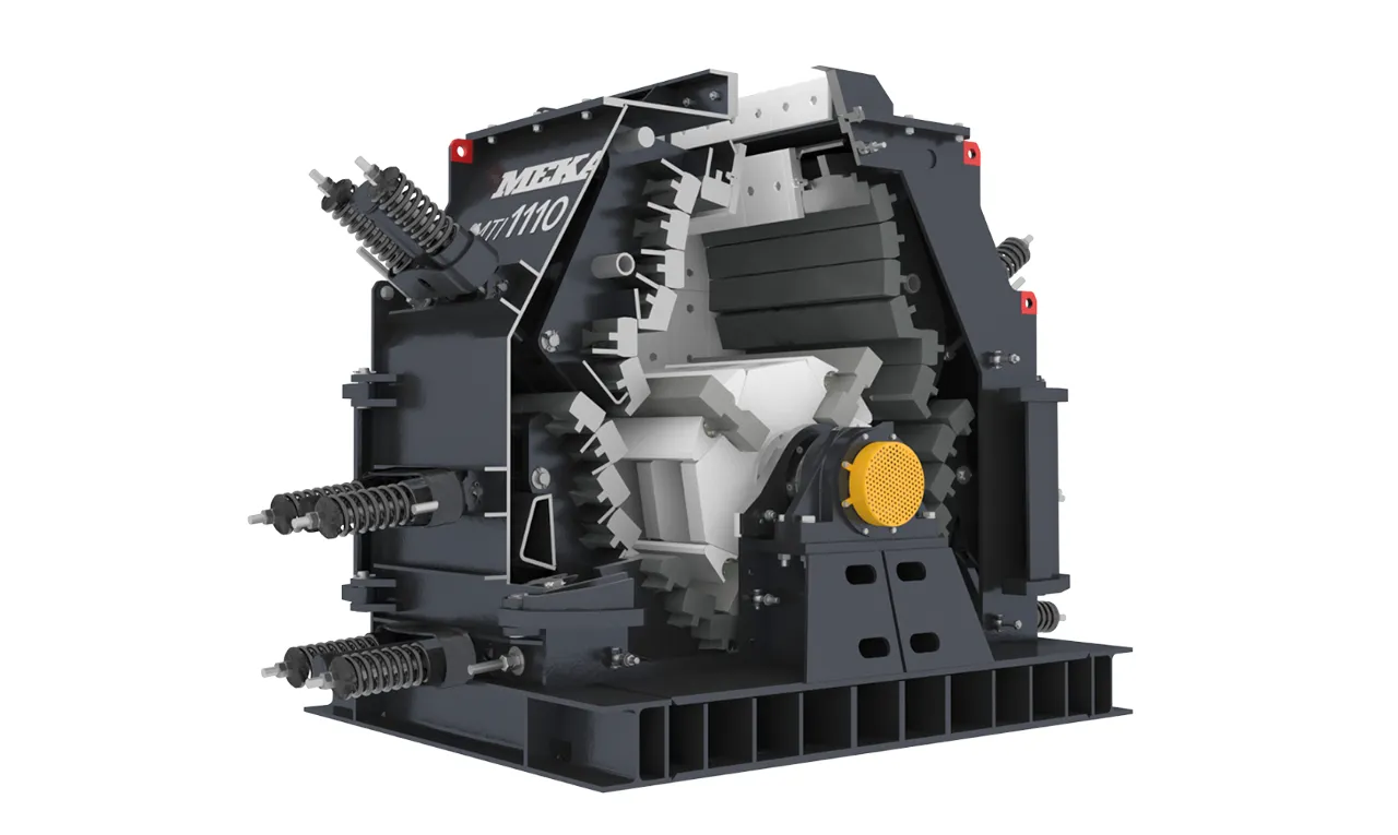
Figure 10 shows views of the reciprocating feeder.


Reciprocating Feeder Capacity

Capacity:
Q = 60 · Be · D · S · n · δ · φ
- Q: capacity, t/h
- Be: width between the hopper skirts, m
- D: bed depth at the feeder discharge, m
The bed depth at the feeder discharge is determined by the designed hopper outlet opening. However, open hoppers are used on reciprocating feeders that feed primary crushers. The bed depth D varies depending on the maximum lump size. This depth is not less than the maximum lump size. If the maximum lump size is between 800 and 1000 mm, the following is suitable:
D ≅ (0.7–1) Be
- S: stroke, m
- n: number of strokes per minute, strokes/min; selected between 15 and 20
- δ: bulk density of the material, t/m³
- φ: fill factor, selected between 0.65 and 0.70
Drive Resistances and Trough Speed
Similar to apron feeders, there are two significant resistances that the reciprocating feeder carriage has to overcome. These are:
- R1: frictional resistance of the carrier rollers, kN
It represents the resistance that the carrier rollers offer against the carriage movement because of the carriage weight and the active material weight. - R2: frictional resistance between the carriage and the material, kN
It represents the frictional resistance that the active material weight exerts against the carriage movement. - RT: total resistance, kN
RT = R1 + R2
R1 = 1.2 · 10 · (M + G) (μd + 2f) / d1
- μ = 0.1 (for bronze-bushed wheels)
- μ = 0.0020–0.0030 (for bearing-mounted wheels)
- f = 0.5
- d1: wheel diameter, mm
- d: wheel shaft diameter, mm
- M: active material weight on the carriage, t
- G: carriage weight, t
- v: trough speed, m/s
v = n · s / 60 - n: number of strokes per minute
- s: stroke, m
Approximate Technical Specifications (Table 11)
Table 11 shows the approximate technical specifications of reciprocating feeders used as primary crusher feeders in crushing and screening plants. The values given are for aggregate with a bulk density of 1.6 t/m³. When the material type and its physical properties change, these specifications also change. These values also apply to an open hopper design.
| Feeder size: deck width × length (mm × mm) | Maximum stroke (mm) | Approx. hydraulic cylinder size: piston diameter × stroke (mm × mm) | Approx. hydraulic tank volume (L) | Power (kW) | Maximum capacity (m³/h) | Maximum feed size (mm) | Approx. number of carrier rollers |
|---|---|---|---|---|---|---|---|
| 1000 × 3500 | 250 | 80 × 300 | 250 | 11 | 300 | 700 | 8 |
| 1200 × 4500 | 350 | 125 × 400 | 400 | 30 | 450 | 1000 | 10 |
| 1500 × 6000 | 350 | 140 × 400 | 400 | 45 | 600 | 1200 | 12 |
| 1800 × 6500 | 400 | 200 × 450 | 1000 | 90 | 1000 | 1500 | 14 |
| 2200 × 7000 | 400 | 250 × 450 | 1000 | 110 | 1200 | 2000 | 14 |
Table 11. Approximate technical specifications of reciprocating feeders (for aggregate with a bulk density of 1.6 t/m³ and an open hopper; the values change when the material type and its physical properties change)
Frequently Asked Questions
What material is a reciprocating feeder used for?
A reciprocating feeder is used for sticky run-of-mine (ROM) material with a high clay and moisture content. It is used as a heavy-duty feeder, particularly in the mining sector. Open hoppers are used on reciprocating feeders that feed primary crushers. The bed depth D at the feeder discharge is not less than the maximum lump size.
How is the stroke of a reciprocating feeder controlled?
The carriage moves back and forth on closely spaced rollers, mostly with a hydraulic cylinder. The amount of this back-and-forth travel, the stroke, is controlled by the stroke of the hydraulic cylinder and by sensors placed at suitable positions. On the backward movement, material in proportion to the amount of travel is discharged to the equipment in front of the feeder.
Which variables determine reciprocating feeder capacity?
Capacity Q, in t/h, is Q = 60 · Be · D · S · n · δ · φ. The variables are the width between the hopper skirts Be, the bed depth at the feeder discharge D, the stroke S, the number of strokes per minute n, the bulk density of the material δ and the fill factor φ. The number of strokes per minute is selected between 15 and 20.
What fill factor and bed depth are used in the capacity calculation?
The fill factor φ is selected between 0.65 and 0.70. The bed depth D at the feeder discharge varies depending on the maximum lump size and is not less than the maximum lump size. If the maximum lump size is between 800 and 1000 mm, D ≅ (0.7–1) Be is suitable, where Be is the width between the hopper skirts.
Which conditions do the values in Table 11 apply to?
Table 11 gives the approximate technical specifications of reciprocating feeders used as primary crusher feeders in crushing and screening plants. The values given are for aggregate with a bulk density of 1.6 t/m³ and also apply to an open hopper design. When the material type and its physical properties change, these specifications also change.
MEKA GLOBAL