Comprehensive Guide to Cone Crushers and Vertical-Shaft Impact Crushers, and Why They Are Used Together in Crushing-Screening Plants
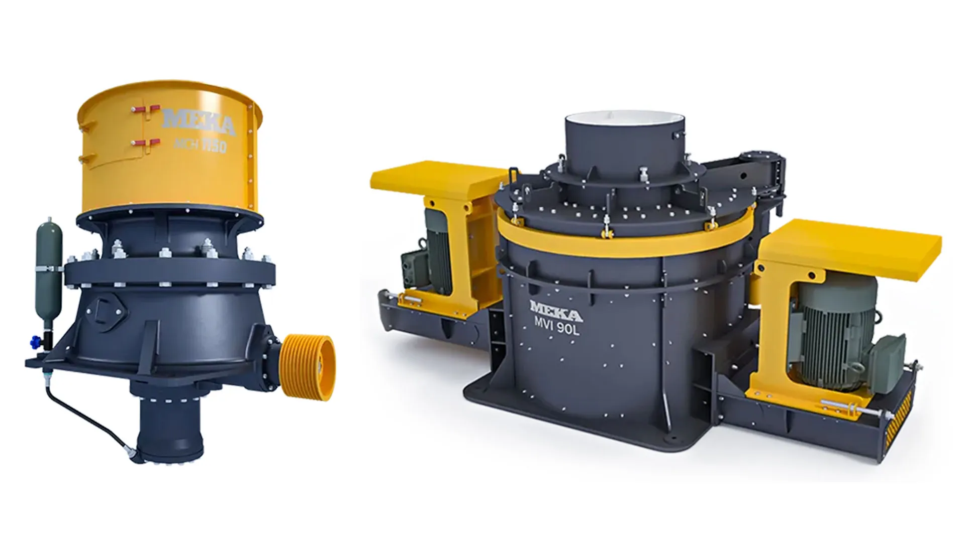
In this article, we will mainly examine the working principles, structure, components, and capacity and power calculations of cone crushers and tertiary-type vertical-shaft impact crushers, which are an inseparable pair as secondary and tertiary crushers in aggregate plants where volcanic rocks such as basalt, granite, diabase and the like are crushed. We will explain the reason why they are used together. We will give examples from the plants in which they are used.
Hydrocone Cone Crushers
Cone crushers are compression crushers.
Figure 1 shows the cross-sectional view of the hydrocone-type cone crusher and the main components that make it up. Bearing-mounted inside the lower body, driven by a bevel-gear system and rotated at a certain gyration speed, is the part called the eccentric; the main shaft of the crusher is mounted eccentrically inside it. The main shaft is also mounted inside the spider bearing located at the top of the upper body. The main shaft rests on the step bearing located on the hydroset piston connected to the lower body of the crusher. This bearing carries the axial loads on the main shaft. On the conical hub connected to the main shaft, the conical moving jaw (mantle) is fixed. On the inner part of the upper body, a fixed jaw (concave) — also conical and with a special form — is fixed.
The hydroset system is a hydraulic cylinder that adjusts the gap between the moving jaw (mantle) and the fixed jaw (concave) — that is, it controls the product size.

During operation, the moving jaw approaches and recedes from the fixed jaw along the full 360° circumference, applying pressure to the material. In other words, we can define the cone crusher as a jaw crusher with an infinite number of jaws.
We see the crushing principle of the cone crusher in Figure 2.

The Rose & English capacity formula
Wi:Bond work index
D:Bowl diameter
LMAX:Open-side setting (OSS)
LMIN:Closed-side setting (CSS)
R:Reduction ratio
K:Statistical factor. For soft materials such as coal and coke, K = 0.5, and for hard materials such as quartz and granite, K = 1
ρs:Specific gravity of the crushed material
The Rose & English motor power formula
P:Motor power,kW
Wi:Bond work index
Q:Capacity,TPH
F80:The size through which 80% of the feed material passes,micron
P80:The size through which 80% of the crushed material passes,micron
Cone crusher gyration speed formula:
n:Cone crusher gyration speed (number of revolutions),RPM
μ: The coefficient of friction between the steel and the crushed material (between 0.2 and 0.3)
d: Maximum product size,cm
α:The angle that the crushing-cone surface makes with the horizontal
Crushing force calculation

n:Gyration speed,RPM
FB:Crushing force,kN
N:Motor power,kW
x:The dimension between the cone lines,mm
α:Half of the cone angle
β:Gyration angle
Tertiary-Type Vertical-Shaft Impact Crushers
The Working Principle of Tertiary-Type Vertical-Shaft Impact Crushers
The rotor of these crushers is closed and completely lined as a stone box. The rotor acts as a high-speed stone pump; by giving a high velocity to the material entering it, it provides a high-speed stream of stone toward the crushing-plate group formed by the rock shelf attached to the body, thereby achieving rock-on-rock crushing. The velocity of the particles thrown from the rotor can rise to values of up to 100 m/s.
In addition to the material entering the rotor, a certain amount of material is also sent in a controlled manner from outside the rotor, providing a density in the crushing chamber and thereby improving the energy transfer. By controlling the amount of this material sent from outside the rotor, together with variables such as the rotor diameter and rotor speed, variables such as product grading, capacity and the amount of wear are brought under control.
Figure 3 shows the crushing principle of tertiary vertical-shaft crushers.

The Main Components of Tertiary-Type Vertical-Shaft Impact Crushers
Figure 4 shows the main components of the tertiary-type vertical-shaft impact crusher. In summary, the main components of these crushers are:
- The crushing chamber group
- The roof group
- The main shaft group
- The base group
It is made up of these groups.

The rotor is like the "heart" of a tertiary-type vertical-shaft impact crusher. Its task is to give the feed material the kinetic energy that will be converted into the stress energy required for it to break — that is, to accelerate it. The feature of tertiary-type crusher rotors is that their rotors are of the closed type; the throw shoes in open rotors are replaced by the stone accumulations that form inside the rotor. The rotor generally has 3 ports with a 120° angle between them. At the port outlets, the stone accumulations form between the tungsten carbide tips and the trail plates located at the edge where the material is thrown out at high speed.
Figure 5 shows the view and components of the tertiary-type vertical-shaft impact crusher rotor; Figure 6 shows the general view and components of the crushing chamber of the tertiary-type vertical-shaft impact crusher.

Capacity and Power Analysis in Tertiary-Type Vertical-Shaft Impact Crushers
Analysis with the Bond formula
In tertiary-type vertical-shaft crushers, when calculating the unit crushing power, the Bond formula gives a result quite different from the actual value. Therefore, as is known, it is a formula based on the work index Wi.
W:The approximate specific energy requirement for crushing,kWh/t
Wi:Work index
P:The square-mesh size through which 80% of the product (the material coming out of the crusher) passes –micron
F:The square-mesh size through which 80% of the material fed to the crusher passes –micron(the fine material should have been screened out of the feed material)
N:Required motor power,kW
Q:Capacity,tonnes/hour
If we examine the product curves in tertiary vertical-shaft impact crushers, in the first part the curve largely proceeds with a low gradient — that is, in this part the reduction ratio is low — and toward the last part the gradient increases and the reduction ratio increases. For this reason, when applying the Bond formula, instead of P80 it is necessary to use a value between P35 and P40.
For quick calculations, Graph 1 can be used.
Table 1 shows the work index and other physical properties of various materials.
| ROCK NAME |
ROCK TYPE |
WORK INDEX Wi |
SPECIFIC GRAV. (t/m³) ρ |
BULK DENS. (t/m³) γ |
ABRASION INDEX Ai |
COMPRESSIVE STRENGTH MPa |
|---|---|---|---|---|---|---|
| Andesite | Volcanic | 16 ± 2 | 2,6-2,8 | 1,6 | 0,5 | 170 - 300 |
| Amphibole | Metamorphic | 16 ± 3 | 2,8 – 3,0 | 1,7 | 0,2 - 0,45 | - |
| Sandstone | Sedimentary | 10 ± 3 | 2,7 | 1,6 | 0,1 - 0,9 | 30-180 |
| Basalt | Volcanic | 20 ± 4 | 2,9 – 3,0 | 1,8 | 0,2 ± 0,1 | 300 – 400 |
| Limestone | Sedimentary | 12 ± 3 | 2,7 | 1,6 | 0,001 – 0,03 | 80 - 180 |
| Carbon | Sedimentary | 14 ± 4 | 1,0 – 1,8 | 0,8 | - | - |
| Clinker | - | - | - | 1,2 | - | - |
| Coke | - | - | - | 0,6 | - | - |
| Diabase | Volcanic | 19 ± 4 | 2,8-2,9 | 1,7 | 0,3 ± 0,1 | 250 - 350 |
| Diorite | Volcanic | 19 ± 4 | 2,7 – 2,8 | 1,6 | 0,4 | 170 – 300 |
| Dolomite | Sedimentary | 12 ± 3 | 2,7 | 1,6 | 0,01 – 0,05 | 50 - 200 |
| Gabbro | Volcanic | 20 ± 3 | 2,9-3,0 | 1,8 | 0,4 | 170 – 300 |
| Gneiss | Metamorphic | 16 ± 4 | 2,7 | 1,6 | 0,5 ± 0,1 | 200 – 300 |
| Granite | Volcanic | 16 ± 6 | 2,7 | 1,6 | 0,55 ± 0,1 | 200 – 300 |
| Hematite | Sedimentary | - | 5,1 | 2,2 – 2,4 | 0,35 ± 0,2 | - |
| Magnetite | Sedimentary | - | 5,7 | 2,2 – 2,4 | 0,50 ± 0,2 | - |
| Marble | Metamorphic | 12 ± 3 | 2,7 | 1,6 | 0,001 – 0,03 | 80 - 180 |
| Porphyry | Volcanic | 18 | 2,7 | 1,6 | 0,1 – 0,9 | 180 – 300 |
| Quartzite | Metamorphic | 16 ± 3 | 2,7 | 1,6 | 0,75 ± 0,1 | 150 – 300 |
| Syenite | Volcanic | 19 ± 4 | 2,7 – 2,8 | 1,6 | 0,4 | 170 – 300 |
| Silex (Hornfels) |
Metamorphic | 18 ± 3 | 2,8 | 1,65 | 0,7 | 150 - 300 |
Table 1 Work index and other physical properties of various materials

The Reason for Using a Cone Crusher as Secondary and a Vertical-Shaft Impact Crusher as Tertiary
Since the cone crusher is a compression crusher, the product obtained from it has internal stresses and hairline cracks. It also has a flaky structure, and its flatness and elongation ratios are not at the desired level. For these reasons, it cannot be directly screened and used in concrete and road construction. The product obtained from the cone crusher needs to be crushed again in a third stage with an impact-type crusher, freed from its internal stresses and made cubical.
As we mentioned earlier, cone crushers are used as effective secondary crushers for hard and abrasive volcanic rocks such as basalt, granite, diabase and river stone. Behind these crushers, a horizontal-shaft impact crusher is generally not used. Instead, vertical-shaft impact crushers designed according to the rock-on-rock crushing principle are used.
Example Plants Where a Cone Crusher Is Used as Secondary and a Vertical-Shaft Crusher as Tertiary
1- A basalt crushing-and-screening plant with a 200 TPH product capacity for producing concrete aggregate
The plant uses an 1100×900 jaw crusher with a 132 kW motor, a cone crusher equivalent to the METSO HP 300 with a 200 kW motor, and a vertical-shaft crusher with a Ø990 rotor diameter and 2×250 kW motors.Figure 5 shows the plant flow diagram, Graph 2 shows the product curve for a 60 m/s tip speed.


2- A river-material crushing-screening-washing plant with a feed size of 0–300 mm
In the plant, river material with a maximum feed size of 300 mm is crushed and concrete aggregate is produced. Being flowing river material, it is not very dirty. After the natural sand is separated, a jaw crusher and a cone crusher are used to reduce the stone to a size that the vertical-shaft crusher can crush. The plant feed capacity is 300 TPH; after 108 TPH of 0–4 natural sand is taken, 192 TPH of crushed-stone concrete aggregate is produced.
Graph 3 shows the river-material feed curve, Figure 6 shows the plant flow diagram, Graph 4 shows the vertical-shaft crusher output curve.


Suphi Yavuz
Senior Mechanical Engineer
Chamber of Mechanical Engineers registration no: 9219
MEKA GLOBAL