What Is a Vibrating Screen? Its Features and Areas of Use
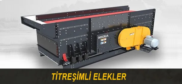
What Is a Vibrating Screen?
Screening holds an important place in almost all mineral processes. The operation of separating a heap containing material of different sizes into at least two or more fractions is called screening (classification). The screening operation is to ensure that the size we want to separate passes through a certain aperture. In this way, the material that can pass through the aperture and the material that cannot are separated from each other. Screens are the machines most used for dimensional classification. Looking at the process industry, many different screens and screening processes are seen. This article focuses on vibrating screens, which are among the most used types of screen in the mining and especially the aggregate production sector.
Screens are generally divided into the three categories seen in Table 1. In fixed-type screens (grizzlies, riffles, sieve bends), no mechanical force is applied to the material to be screened; screening takes place only through the effect of gravity. Trommels and roller screens can be given as examples of rotary-type screens. A trommel (Table 1, image on the right) works on the principle of the rotation of a drum with holes on the screen surface. Screening takes place as the material loaded into the screen passes through the holes. A roller screen has a structure with several synchronously or asynchronously rotating rollers arranged one after another. It works on the principle that the material to be screened falls down through the gaps between the rollers. A roller screen is shown in Figure 1.

The screening types are divided into categories according to material size (Figure 1). These categories can be summarized as follows:
400 micron – 2 mm extra fine, 2–5 mm wet applications, 5–65 mm typical classification, 65–250 mm large material classification, 250–450 mm coarse screening, 450–915 mm extra coarse

1.1 What Is G-Force?
Inclined screens operate in the 3–4 G range and horizontal screens in the 4–5 G range. So, have you ever thought about it? When you reach 100 km/h with your car in about 8 seconds, how much G acts on you? The answer to this question is 0.58 G. What is G-force and what does it have to do with screens?
When we say that 5 G acts on a screen, it means that an acceleration of 5 times the gravitational acceleration acts on the system. Although the gravitational acceleration varies according to your location on Earth, it is taken as 9.81 m/s². That is, 5 G is 5 × 9.81 = 49.05 m/s².
1.2 The Working Principle of Vibrating Screens
Vibrating screens are the most preferred type of screen in industry. They generally consist of a screen body, a drive mechanism and an elastic system.
1.2.1 The Screen Body
Vibrating screens are the most preferred type of screen in industry. They generally consist of a screen body, a drive mechanism and an elastic system.

1.2.2 The Drive System
One of the most critical elements of a screen is the drive system. To understand drive systems, it is important to know the working principle of the screen. Screens are vibrated by means of the centrifugal force created by rotating eccentric weights at a certain speed. The working principle of the drive system is shown in Figure 3.

The mounting position of the eccentric weight on the screen body affects the vibration pattern. In single-drive inclined screens, the drive mechanism is placed at a position close to the centre of gravity of the screen. In this way, the vibration is made equal at every point of the screen.
1.2.3 How Is G Calculated?
You can use the following formula to calculate the G of your system.

For example: the G of a screen operating at 900 RPM with a stroke of 9 mm is calculated as follows:

You can also determine the G value using Graph 1.

If your screen or feeders operate outside the recommended G range, then two risks await you. For inclined screens the 3–4 G range, for horizontal screens the 4–5 G range, and for feeders the 4–5 G range have been proven suitable by experience up to now. If the G value is lower than the recommended value, a decline in screening efficiency and capacity, and clogging of your screens, can occur. If it is higher than the specified value, the mechanical structures can be overstressed, and cracking in the structure and a reduction in bearing life can be seen.
1.2.4 The Elastic System
As elastic-system elements in screens and feeders, helical steel springs, rubber blocks, and elements in which rubber components are placed in a special structure can be used. Helical steel springs are the most used and most economical elastic-system element in screens and feeders. The elastic-system elements are shown in Figure 2.

The advantages of rubber blocks over the helical steel spring:
- Because the spring rate of rubber springs changes according to the load acting on them, they provide a constant natural frequency under variable loads, thereby providing good isolation.
- They have high load-carrying capacities.
- Because the spring rate in the horizontal direction is lower than in the vertical direction, they provide good isolation in the horizontal direction.
- In humid and corrosive environments, they are more efficient than steel springs.
- They produce less noise.
1.3 Frequency, Stroke and Vibration Pattern
Vibrating screens have three important operating parameters. These are: the shape of the vibration motion, the stroke and the frequency. While these properties can be changed simply on some screens, on other screens changing them after manufacture is quite difficult in the plant environment. While a screen vibrates, it moves along a certain trajectory. This trajectory is the shape of the vibration motion. Twice the amplitude is called the stroke. The stroke is the distance between the two points on the trajectory that are farthest from each other. To get information about how the stroke is measured, you can review the videos on the MEKA GLOBAL YouTube page. Examples of stroke are shown in Table 2. Frequency indicates the number of occurrences of an event per unit of time. The frequency in screens indicates how many times per second the screen passes a point on the trajectory it follows. It is directly related to the rotation speed of the eccentric weights.

1.4 What Is Screening?
In all screens, the basic principle is the same. Particles smaller than the screen aperture can pass beneath the screen deck, and these particles are called undersize; materials larger than the aperture leave the system without passing through the screen deck, and these materials are called oversize (Figure 4). As the probability of particles passing through the aperture increases, the screening efficiency rises. The path that the particles follow on the screen is shown in Figure 5.
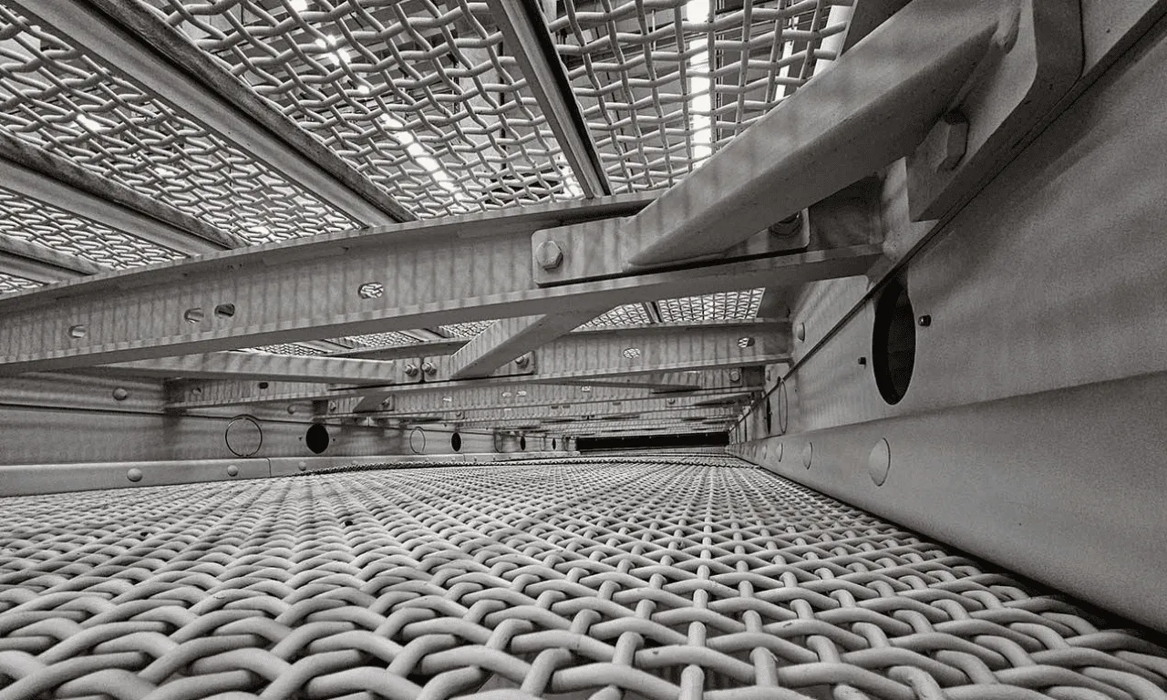
The most frequently used vibrating screens have 2, 3 or 4 decks. On each deck, structures called frames carry the screen deck (screen media). If the material is small enough to pass through the aperture on the deck it is on, it passes to the deck below; if not, it leaves the system at the end of the deck. A chute at the screen's discharge point conveys the oversize material coming from each deck to the next stage without mixing them together.


1.5 Stratification
Another important factor in screening is stratification. The material sent to the screen, at the point where it is first poured, has coarse and small particles mixed together. For screening to take place, the small particles need to slip out from among the coarse materials and reach the screen deck. After the mixed material advances for a while on the screen surface, thanks to the vibration motion, the small particles come to be positioned at the bottom and the coarse particles on top of the heap; this situation is called stratification. Stratification is shown in Figure 6.
Bed depth is a parameter that must be controlled in the screening process in relation to stratification. The general rule for bed depth is that, for materials with a bulk density of 1.6 t/m³, it should not be more than 4 times the screen aperture, and for those with a lower density, not more than 3 times. The bed depth is shown in Figure 6. The factors affecting stratification are given below:
- The ability of the material to move on the screen is important for stratification. This changes depending on the shape of the material. Round materials move faster on the screen deck, while flat materials move relatively more slowly. Other factors affecting the material speed are the properties and the inclination of the screen deck.
- The vibration frequency, amplitude and type of motion of the screen.
- A high amount of moisture on the surface of the material adversely affects stratification.

1.6 Screen Types and Areas of Use
Screens can be of very various types according to their place of use. The place of use and screen types are given in Table 3.

1.6.1 Inclined Screen
Inclined screens are the most used type of screen. Inclined screens can be between 15° and 30°. As in all screens, the screen body operates on steel or rubber springs. The operating stroke of this type of screen can generally be between 8 mm and 12 mm. When the amount of the eccentric weights is increased a high stroke is obtained, and when it is decreased a low stroke. This type of screen can have 2, 3 or 4 decks, so that 3 different products can be taken from a 2-deck screen, 4 from a 3-deck screen and 5 from a 4-deck screen. An inclined screen is shown in Figure 3.

1.6.2 Horizontal Screen
Horizontal screens (Figure 4) have a more complex structure than inclined screens. These screens can be positioned either parallel to the ground or at angles varying between 0° and 5°. The most important feature of horizontal screens is that they can perform an elliptical vibration motion (Figure 7) at the desired attack angle and stroke. The attack angle, stroke and operating speed of this vibration motion can be easily changed.


The triple drive mechanism is created by synchronizing three systems — similar to the drive system in inclined screens — with gears (Figure 5).

Thanks to this system, the screen performs an elliptical motion, which is a combination of both circular and linear motion. The biggest advantage of the elliptical motion is that it is more successful in preventing clogging of the screen deck, and because the screen deck is horizontal, the screen aperture can be used more efficiently. As seen in Figure 8, because the aperture is larger in horizontal screens, the amount of correctly sized material within the product will be greater, which means an increase in efficiency. In this case, at first glance one might think that this could be achieved by fitting inclined screens with a screen mesh larger than the desired aperture; however, in that case there is a possibility that material larger than desired could mix into the product we obtain.

The stroke of horizontal screens varies between 14 and 20 mm. It has a higher stroke and G value than other screens.
1.6.3 Banana Screen
The banana screen (Figure 6) got this name because of its curved frame structure. Unlike conventional flat frame structures, in banana screens the decks are arranged at angles varying between 0° and 45°. Thanks to this structure, banana screens have a high capacity, a low bed depth and a high material speed.

Banana screens are driven by means of the drive mechanism placed on the screen. Thanks to this drive mechanism, linear motion takes place. However, because there are different inclinations along a deck, the material has different speeds at the loading, middle and discharge parts of the screen. The high inclination at the feed part enables the material to stratify faster, while the low inclination at the discharge part allows the material to spend more time on the screen (Figure 9), and screening efficiency thus rises.
1.6.4 Dewatering Screen
Dewatering screen (Figure 7) is used to separate the water from fine material that contains a high amount of water. A vibration motion is created by means of vibromotors placed on the screen. The screen's inclination is opposite to the material flow direction and between 0° and 5°. The operating speed of this type of screen is generally around 1000–1500 rpm.
1.6.4 Dewatering Screen
Dewatering screen (Figure 7) is used to separate the water from fine material that contains a high amount of water. A vibration motion is created by means of vibromotors placed on the screen. The screen's inclination is opposite to the material flow direction and between 0° and 5°. The operating speed of this type of screen is generally around 1000–1500 rpm.

It performs linear vibration by means of two counter-rotating vibromotors. Thanks to this vibration, as the water passes through the screen aperture, the oversize material advances toward the discharge part. As the material leaves via the inclination that is opposite to the feed direction, the cake layer that forms (Figure 8) acts as a filter, so that particles that might pass through the aperture are retained. Dewatering screens have a higher G than other screens. For an efficient dewatering operation, it is appropriate for the screen to operate in the 5–6 G range.

1.6.5 Fine Material Screen
The fine material screen (Figure 9) can screen material fed at a size of 0–5 mm down to 200 micron. In this type of screen, the sub-frames are connected to the body with vibration-amplifying structures, so that the sub-frames vibrate at a much higher frequency and amplitude than the screen body. In this way, low-sized material can be screened with high capacity and efficiency.

Another type of screen used for fine materials is the high-frequency screen. In this type of screen, thanks to the small-sized and numerous vibromotors connected beneath the sub-frames, the sub-frame is vibrated at a much higher frequency than the screen body. In this way, the number of contacts the material makes with the screen surface increases and efficient screening is carried out (Figure 10).

Another screen used for fine-material screening processes is the rotary screen (Figure 10). In this screen, unlike conventional screens, the material is fed from the centre and advances toward the edges. It is used especially frequently in food-product manufacturing.

1.6.6 Grizzly Screen
Grizzly screens (Figure 11) is used to screen heaps with quite large particle sizes. Grizzly screens take their name from the parallel bars (grizzly bars) on their upper deck. These screens are generally used before the crushing operation to prevent small particles from entering the crusher and reducing efficiency. The distance between the bars can be adjusted according to the size of the material to be screened. The bar opening is generally larger than 50 mm and, in some applications, can go up to 300 mm. The inclination of grizzly screens can be between 15° and 20°.

The bars are made of wear-resistant material. Manganese-alloy cast steel is generally a preferred manufacturing method for the bars. The distance between the bars widens from the feed toward the discharge direction, so that the screened material is prevented from getting stuck between the bars. Because it will be subjected to large loads, the side plates and body structure of the grizzly screen are designed to be suitable for heavy duty.
MEKA GLOBAL