Horizontal Oval (Elliptical) stroke Screen or Inclined Circular stroke Screen?
Choosing the Right Screen for Your Application
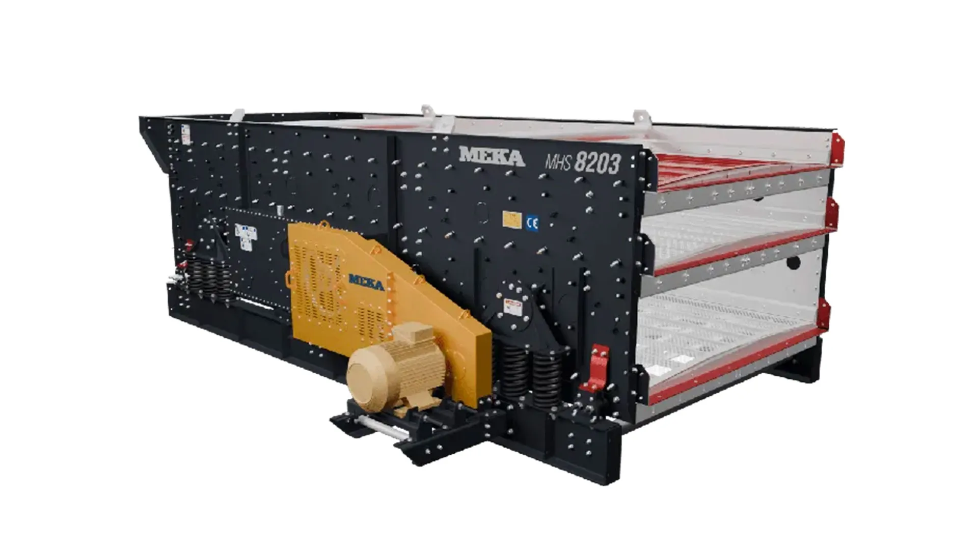
In crushing and screening plants, separating material by gradation depends directly on the right screen selection. This article explains the differences between the two screen types most used in aggregate plants — the conventional circular motion vibrating screen and the 3-shaft controlled-vibration elliptical (oval) motion screen — the reasons each is preferred, and which one to choose for which application.
Working Principles of Circular, Linear, and Elliptical Motion Vibrating Screens
Circular motion vibrating screens use a circular vibration to screen the material. Because gravity is required to move the material along the screen media, these screens are designed at an angle. As a particle travels across the screen panel it tumbles. The tumbling action prevents the particle from plugging the aperture and allows smaller particles to pass through.
Linear motion horizontal screens (or screens at a very low incline) use a back-and-forth motion at a positive angle to the vertical. The screen panel lifts the particle and lets it fall forward. This motion conveys the particle along the panel. Because the screen runs horizontally, the particle falling vertically uses the full aperture for sizing, which makes the passage of undersize material easier.
Oval motion vibrating screens combine the rotational behavior of circular motion screens with the full-aperture utilization of linear motion screens. As a result, they deliver higher screening efficiency and higher capacity than circular or linear motion screens of the same size.
Figure 1 illustrates these three types of stroke motions.

Reasons to Choose Elliptical (Oval) Motion Vibrating Screens
The main reasons to choose a controlled-vibration oval motion screen are:
- High capacity
- Controllable vibration parameters
- Robust, long-service-life construction
High Capacity
The capacity formula for vibrating screens is given below. This is the VSMA (Vibrating Screen Manufacturers Association) formula:
A: Specific screening capacity, TPH/ft² (the screen's screening capacity per unit area).
The factors used in this formula are:
B: Basic capacity, TPH/ft² — Diagram 1
S: Slope factor — Diagram 2
D: Deck location factor — Diagram 3
V: Oversize factor (fraction of feed larger than the aperture) — Diagram 4
H: Half-size factor (fraction of feed smaller than half the aperture) — Diagram 5
T: Aperture shape factor — Diagram 6
K: Material condition factor — Diagram 7
Y: Wet-screening factor — Diagram 8
P: Particle shape factor — Diagram 9
W: Bulk-density (material weight) factor — Diagram 10
O: Open-area factor — Diagram 11
F: Screening efficiency factor — Diagram 12


More recently — particularly after the introduction of 3-shaft oval motion screens — the VSMA formula has been extended as follows:
The new factors are:
TYP: Vibration stroke type factor — Diagram 13
STR: Stroke length factor — Diagram 14
TIM: Vibration angle factor — Diagram 15
RPM: Vibration speed (RPM) factor — Diagram 16
NEA: Near-size factor — Diagram 17
BED: Bed depth (material thickness) factor — Diagram 18
These factors are read from the charts below.


The most important of these new factors is TYP, the vibration stroke type factor. Diagram 13 gives the TYP values. As can be seen, the stroke type alone gives oval motion screens a 12% capacity gain.
In addition, Figure 2 illustrates the extra capacity that comes from operating the screen horizontally. The same effect appears in Diagram 2 (the S – slope factor): the horizontal screen delivers a 10% capacity gain over the inclined screen.
Taking all these factors together, the capacity of an oval motion screen is roughly 30% higher than that of an inclined, circular motion screen of the same size.
Controllable Vibration Parameters
On 3-shaft oval motion screens, the following parameters can be easily adjusted to the material being screened:
- Stroke length
- Vibration angle
- Vibration frequency
On other screens the vibration angle cannot be changed. However, adjusting the vibration angle to suit the material's structure and gradation produces large gains in both capacity and screening efficiency.
This is also visible in Diagram 14 (STR), Diagram 15 (TIM) and Diagram 16 (RPM).
Figure 3 shows how stroke length and vibration angle change with the material being screened. Figure 4 shows how the vibration frequency is changed using shims. Table 1 shows how stroke length changes as cylindrical counterweights are added.


In summary, the ability to control vibration parameters on a 3-shaft oval motion screen according to the material being screened increases screening efficiency by 5-10% compared with a screen of the same size that does not offer this control.
Robust, Long-Service-Life Construction
Thanks to a dedicated bearing housing design in which the inner race of the bearing stays fixed while the outer race rotates, the loads are distributed over a wider area, which extends bearing service life. The screen body itself is also very robust.
In short, sound design and a robust body structure significantly extend the screen's service life.
Reasons to Choose Circular Motion Vibrating Screens
Despite their disadvantages, circular motion vibrating screens of the same size and deck count have lower manufacturing, maintenance and operating costs. For this reason, many aggregate producers prefer them, particularly on plants with relatively low-capacity requirements.
References
- TEREX CEDARAPIDS, TSH Horizontal Screens, Form 25524.
- TEREX CEDARAPIDS, Eljay Legacy Series Screens, Bulletin EJLS-1.
- Suphi Yavuz, Titreşimli Besleyiciler ve Titreşimli Elekler (Vibrating Feeders and Vibrating Screens), Gece Kitaplığı, 2017, ISBN 978-605-288-214-6.
- Larry Olsen and Bob Carnes, Technical Paper T-JCI-205: Screen Capacity.
Suphi Yavuz
Senior Mechanical Engineer (M.Sc.)
MMO (Chamber of Mechanical Engineers of Turkey) Registration No.: 9219
MEKA GLOBAL