
Standard Wire Mesh Sizes for Vibrating Screens: Selection and Sizing Guide
Standard Wire Mesh Sizes for Vibrating Screens: Selection and Sizing Guide
Wire mesh is the working surface of every vibrating screen. It defines the cut point, sets the maximum capacity the deck can deliver, and dictates how often a plant has to stop for changeouts. Choosing the wrong mesh costs production: an opening that is too small blinds and starves the screen; an opening that is too large lets oversize pass and forces a costly re-screen.
This guide consolidates the standard square-mesh sizes used on vibrating screens — every size from 1 × 1 mm fines screens up to 120 × 120 mm scalper decks — and explains how to read the four parameters that matter: opening, wire diameter, unit weight, and open area ratio. It then translates those numbers into selection rules: how to match mesh to a target particle cut, how to balance throughput against wire life, and which mesh material survives which feed. A bonus section covers DIN 2440 and DIN 2441 pipe standards used for screen frames. Use the sortable chart and cutoff selector at the end of the article to spec replacement mesh against your own gradation.
Wire Mesh Sizing for Vibrating Screens
Vibrating Screen Mesh Basics
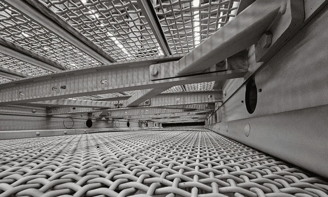
A vibrating-screen mesh is a woven steel cloth tensioned across the deck. Material fed onto the deck stratifies under vibration; particles smaller than the opening drop through to undersize, while oversize travels along the deck to the discharge end. Three parameters set the behaviour of every mesh, and one derived ratio combines them into the figure that drives capacity calculations.
Three Critical Mesh Parameters: Opening (W), Wire Diameter (d), and Open Area Ratio

W is the screen opening — the clear distance between adjacent wires, measured in millimetres. d is the screen wire diameter, also in millimetres. The handbook reference table on page 136 lists every standard pairing of W and d in commercial production. From these two values, the third critical figure — open area ratio — is calculated:
Open Area Ratio (%) = ( W² / (W + d)² ) × 100
In LaTeX form this is: \(\eta_{\text{open}} = \frac{W^2}{(W+d)^2} \times 100\). The expression captures a simple geometric truth: the open area is the square of the opening divided by the area of one full pitch, where each pitch is opening plus one wire diameter. A 10 × 10 mm mesh with 3 mm wire therefore has an open area of 100 / 169 = 59 %, exactly the value listed in the handbook.
How Mesh Size Determines Cutoff Point
Opening W is not the same as cut size. A particle just smaller than W has only a narrow geometric window in which it can present squarely to the opening, so screening cuts sharper than W only at the lower end of the size distribution. The convention is to size the opening 20–25 % above the target separation size — known as the 80 % rule — so the bulk of the desired fraction reports to undersize without blinding the deck.
The Standard Wire Mesh Size Chart
The reference table below is a direct transcription of handbook page 136, covering opening sizes from 1 × 1 mm up to 120 × 120 mm. For most opening sizes, two or three wire diameters are listed: a finer wire gives more open area but lower strength; a heavier wire trades capacity for life. The full sortable / filterable HTML version is supplied in the code block at the end of this article.
Square Mesh Sizes from 1 × 1 mm to 120 × 120 mm
| Opening W (mm) | Wire Diameter d (mm) | Unit Weight (kg/m²) | Open Area Ratio (%) |
| 1×1 | 0.75 | 4.2 | 33 |
| 1.25×1.25 | 1 | 5.8 | 31 |
| 1.5×1.5 | 1 | 5.2 | 36 |
| 1.75×1.75 | 1 | 4.8 | 40 |
| 2×2 | 1 | 4.4 | 44 |
| 2×2 | 1.2 | 5.9 | 39 |
| 2×2 | 1.5 | 8.4 | 33 |
| 2.5×2.5 | 1.2 | 5.1 | 46 |
| 2.5×2.5 | 1.5 | 7.4 | 39 |
| 3×3 | 1.5 | 6.5 | 44 |
| 3×3 | 1.8 | 8.8 | 39 |
| 3×3 | 2 | 10.5 | 36 |
| 3.5×3.5 | 1.5 | 5.9 | 49 |
| 3.5×3.5 | 1.8 | 8.0 | 44 |
| 3.5×3.5 | 2 | 9.5 | 40 |
| 4×4 | 1.5 | 5.4 | 53 |
| 4×4 | 2 | 8.7 | 44 |
| 4×4 | 2.2 | 10.2 | 42 |
| 4×4 | 2.5 | 12.5 | 38 |
| 4.5×4.5 | 1.5 | 4.9 | 56 |
| 4.5×4.5 | 2 | 8.0 | 48 |
| 4.5×4.5 | 2.5 | 11.7 | 41 |
| 5×5 | 1.5 | 4.5 | 59 |
| 5×5 | 2 | 7.5 | 51 |
| 5×5 | 2.2 | 8.8 | 48 |
| 5×5 | 2.5 | 10.9 | 44 |
| 5×5 | 3 | 14.7 | 39 |
| 5.5×5.5 | 2 | 7.0 | 54 |
| 5.5×5.5 | 2.5 | 10.2 | 47 |
| 5.5×5.5 | 3 | 13.9 | 42 |
| 6×6 | 2 | 6.5 | 56 |
| 6×6 | 2.5 | 9.6 | 50 |
| 6×6 | 3 | 13.1 | 44 |
| 6×6 | 3.5 | 16.8 | 40 |
| 7×7 | 2.5 | 8.6 | 54 |
| 7×7 | 3 | 11.8 | 49 |
| 7×7 | 3.5 | 15.3 | 44 |
| 8×8 | 2 | 5.2 | 64 |
| 8×8 | 2.5 | 7.8 | 58 |
| 8×8 | 3 | 10.7 | 53 |
| 8×8 | 3.5 | 13.9 | 48 |
| 8×8 | 4 | 17.4 | 44 |
| 9×9 | 2.5 | 7.1 | 61 |
| 9×9 | 3 | 9.8 | 56 |
| 9×9 | 3.5 | 12.8 | 52 |
| 9×9 | 4 | 16.1 | 48 |
| 10×10 | 2.5 | 6.5 | 64 |
| 10×10 | 3 | 9.1 | 59 |
| 10×10 | 3.5 | 11.9 | 55 |
| 10×10 | 4 | 14.9 | 51 |
| 10×10 | 5 | 21.8 | 44 |
| 11×11 | 3 | 8.4 | 62 |
| 11×11 | 4 | 14.0 | 54 |
| 11×11 | 5 | 20.4* | 47 |
| 12×12 | 3 | 7.8 | 64 |
| 12×12 | 4 | 13.1 | 56 |
| 12×12 | 5 | 19.2 | 50 |
| 13×13 | 3 | 7.4 | 66 |
| 13×13 | 4 | 12.3 | 58 |
| 13×13 | 5 | 18.2 | 52 |
| 14×14 | 3.5 | 9.2 | 64 |
| 14×14 | 4 | 11.6 | 60 |
| 14×14 | 5 | 17.2 | 54 |
| 15×15 | 3.5 | 8.7 | 66 |
| 15×15 | 4 | 11.0 | 62 |
| 15×15 | 5 | 16.4 | 56 |
| 15×15 | 6 | 22.4 | 51 |
| 16×16 | 3.5 | 8.2 | 67 |
| 16×16 | 4.5 | 12.9 | 61 |
| 16×16 | 5 | 15.6 | 58 |
| 16×16 | 6 | 21.4 | 53 |
| 17×17 | 4 | 10.0 | 66 |
| 17×17 | 5 | 14.9 | 60 |
| 17×17 | 6 | 20.5 | 55 |
| 18×18 | 4 | 9.5 | 67 |
| 18×18 | 4.5 | 11.8 | 64 |
| 18×18 | 5 | 14.2 | 61 |
| 18×18 | 6 | 19.6 | 56 |
| 19×19 | 5 | 13.6 | 63 |
| 19×19 | 6 | 18.8 | 58 |
| 20×20 | 4 | 8.7 | 69 |
| 20×20 | 5 | 13.1 | 64 |
| 20×20 | 6 | 18.1 | 59 |
| 20×20 | 7 | 23.7 | 55 |
| 21×21 | 5 | 12.6 | 65 |
| 21×21 | 6 | 17.4 | 60 |
| 22×22 | 5 | 12.1 | 66 |
| 22×22 | 6 | 16.8 | 62 |
| 22×22 | 7 | 22.1 | 58 |
| 23×23 | 5 | 11.7 | 67 |
| 23×23 | 6 | 16.2 | 63 |
| 23×23 | 7 | 21.3 | 59 |
| 24×24 | 5 | 11.3 | 68 |
| 24×24 | 6 | 15.7 | 64 |
| 24×24 | 7 | 20.7 | 60 |
| 25×25 | 4 | 7.2 | 74 |
| 25×25 | 5 | 10.9 | 69 |
| 25×25 | 6 | 15.2 | 65 |
| 25×25 | 7 | 20.0 | 61 |
| 25×25 | 8 | 25.4 | 57 |
| 26×26 | 6 | 14.7 | 66 |
| 26×26 | 7 | 19.4 | 62 |
| 26×26 | 8 | 24.6 | 58 |
| 27×27 | 6 | 14.3 | 67 |
| 27×27 | 7 | 18.9 | 63 |
| 27×27 | 8 | 23.9 | 60 |
| 28×28 | 6 | 13.9 | 68 |
| 28×28 | 7 | 18.3 | 64 |
| 28×28 | 8 | 23.3 | 60 |
| 30×30 | 5 | 9.3 | 73 |
| 30×30 | 6 | 13.1 | 69 |
| 30×30 | 7 | 17.3 | 66 |
| 30×30 | 8 | 22.0 | 62 |
| 30×30 | 10 | 32.7 | 56 |
| 32×32 | 6 | 12.4 | 71 |
| 32×32 | 8 | 20.9 | 64 |
| 32×32 | 10 | 31.1 | 58 |
| 35×35 | 6 | 11.5 | 73 |
| 35×35 | 8 | 19.5 | 66 |
| 35×35 | 10 | 29.1 | 60 |
| 38×38 | 8 | 18.2 | 68 |
| 38×38 | 10 | 27.3 | 63 |
| 40×40 | 7 | 13.6 | 72 |
| 40×40 | 8 | 17.4 | 69 |
| 40×40 | 10 | 26.2 | 64 |
| 45×45 | 8 | 15.8 | 72 |
| 45×45 | 10 | 23.8 | 67 |
| 50×50 | 8 | 14.4 | 74 |
| 50×50 | 10 | 21.8 | 69 |
| 50×50 | 12 | 30.4 | 65 |
| 55×55 | 8 | 13.3 | 76 |
| 55×55 | 10 | 20.1 | 72 |
| 60×60 | 8 | 12.3 | 78 |
| 60×60 | 10 | 18.7 | 73 |
| 60×60 | 12 | 26.2 | 69 |
| 65×65 | 10 | 17.4 | 75 |
| 65×65 | 12 | 24.5 | 71 |
| 70×70 | 10 | 16.4 | 77 |
| 70×70 | 12 | 23.0 | 73 |
| 75×75 | 10 | 15.4 | 78 |
| 75×75 | 12 | 21.7 | 74 |
| 80×80 | 10 | 14.5 | 79 |
| 80×80 | 12 | 20.5 | 76 |
| 90×90 | 10 | 13.1 | 81 |
| 90×90 | 12 | 18.5 | 78 |
| 100×100 | 10 | 11.9 | 83 |
| 100×100 | 12 | 16.8 | 80 |
| 120×120 | 10 | 10.1 | 85 |
| 120×120 | 12 | 14.3 | 83 |
Reading the Reference Table: Opening, Wire Diameter, Unit Weight, Open Area Ratio
Each row is a complete mesh specification. The opening W is the clear gap, the wire diameter d is the structural element, the unit weight is mass per square metre of installed mesh (used for transport, deck loading, and replacement quoting), and the open area ratio is the fraction of the deck that is hole.
Where multiple rows share the same opening size, they represent valid alternatives — same separation cut, different durability and capacity. Coarse, low-impact feeds favour the lighter wire; abrasive or high-tonnage feeds justify the heaviest wire offered for that opening.
Selecting the Right Mesh for Your Material
Particle Size to Mesh Size: The 80% Rule
The mesh opening should sit roughly 1.25 × the target cutoff size. Re-arranged: W ≈ 1.25 × d₅₀, where d₅₀ is the target separation size (the size at which 50 % of feed reports to undersize). The factor 1.25 accommodates particles that approach the opening at oblique angles, fines that bridge across the wire, and the fact that woven wire deflects under load. Going tighter than 1.25 × choking results; going wider lets significant oversize pass and degrades product quality.
Mesh for Common Aggregate Cuts
The matrix below maps the most common aggregate gradations to a starting mesh size from the standard chart. These are starting points; verify against laboratory sieve analysis on a representative feed sample before committing to mesh procurement.
| Material / Cut | Target Particle Size | Suggested Mesh Opening W | Notes |
| Sand (concrete fines) | 0–4 mm | 4–5 mm | Slightly oversized; sand passes freely while + 5 mm is rejected |
| Fine gravel | 4–8 mm | 8–10 mm | Common asphalt fine fraction cut |
| Medium gravel | 8–16 mm | 16–18 mm | Concrete coarse aggregate split |
| Coarse aggregate | 16–32 mm | 32–35 mm | Top fraction for ready-mix concrete |
| Railway ballast / large rip-rap | 32–63 mm | 63–80 mm | DIN ballast Class I/II prep |
Mesh Type Selection: Square, Rectangular, Slotted
Square mesh — equal opening dimension in both directions — is the standard, all-purpose choice and the basis of the handbook chart. Rectangular and slotted meshes elongate the opening in the direction of travel, raising open area at the same wire diameter and resisting blinding from elongated particles such as flakes and chips. Capacity gains of 15–25 % at equivalent cut are typical, but cuts are less precise because particles pass on their long axis. Use slotted patterns where the feed is flat or splintered, or where deck capacity limits production; stay with square mesh where cut precision determines product spec.
Wire Mesh Material Selection
Wire material selection is independent of size selection and is driven by feed conditions: hardness, abrasiveness, moisture, and chemistry. Four families dominate aggregate and mining service.
Carbon Steel — General Aggregate, Lowest Cost
Standard mesh for non-corrosive aggregate: limestone, granite, basalt, gravel, recycled concrete. Service life runs 2–6 months on hard abrasive feeds; soft feeds extend that to a year or more. Lowest initial cost — the default unless feed conditions argue otherwise.
Stainless Steel — Corrosive and Wet Service
Specified where moisture, salinity, food-grade requirements, or chemical exposure rule out carbon steel. AISI 304 handles most wet aggregate and dewatering duty; AISI 316 is used where chlorides are significant. Typically delivers 2–3× the life of carbon steel in genuinely corrosive service; on dry aggregate it offers no advantage.
High-Manganese Steel — Hard Rock and High-Abrasion Service
Hadfield-type austenitic manganese steel (12–14 % Mn) work-hardens under impact and resists abrasion through surface deformation. On hard rock such as granite, basalt, and quartzite, manganese-steel mesh typically lasts 3–5× longer than carbon steel — economics favour it whenever changeover downtime cost exceeds the mesh price differential.
Polyurethane and Rubber Alternatives — When Wire Fails
Modular polyurethane and rubber panels replace woven wire entirely with cast / moulded apertures. Where wire blinds, pegs, or wears prematurely, these panels can multiply life by an order of magnitude and cut noise by 5–10 dB at 2–4× the initial cost. Mix-and-match strategies — wire on the impact-heavy upper deck, polyurethane on the blinding-prone lower deck — are common on modern aggregate plants. See [link to: /products/screening-plants/inclined-vibrating-screen] and [link to: /products/screening-plants/horizontal-vibrating-screen].
Open Area Ratio and Screen Capacity
Why Open Area % Matters
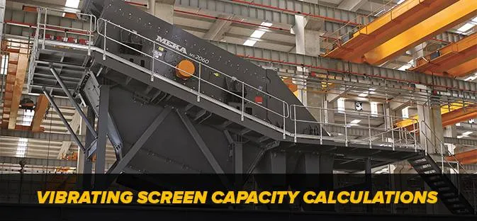
Screen capacity scales almost linearly with open area ratio at a given cut size and material. A deck with 50 % open area passes roughly twice the volume of one with 25 % open area before overloading. The open-area column of the reference table is therefore as important as the opening size — it sets the upper bound on tonnes-per-hour the screen can deliver. For deeper treatment of capacity calculation, see [link to: /blog/vibrating-screen-capacity-calculations].
Trade-off: Bigger Opening = Less Wire = Higher Capacity but Lower Strength
Within a single opening size, higher open area always corresponds to a finer wire. Reading the 25 × 25 mm row of the reference table: 4 mm wire gives 74 % open area at 7.2 kg/m²; 8 mm wire gives only 57 % open area at 25.4 kg/m². The first option maximises capacity but fails fast under hard-rock impact; the second option lasts but cuts deck capacity by 23 %. Rule of thumb: choose the heaviest wire that still meets capacity targets — durability gains usually outweigh the marginal throughput loss.
Mesh Lifespan and Replacement
Wear Patterns and Failure Modes
Wire mesh fails through four mechanisms, often in combination. Wire elongation is gradual stretching under tension and impact — opening size grows progressively, letting oversize through. Edge cracks initiate where the mesh clamps to the frame, in the high-cycle fatigue zone. Blinding is near-size particles wedged in openings — common with damp or sticky feeds at fine cuts, visible as capacity loss long before any wire breaks. Centre wear is localised diameter loss directly under the feed box.
When to Replace
- Visible cracks at the frame edge or across the deck — replace immediately.
- Opening deformation greater than 10 % of nominal W — product gradation is out of spec.
- Persistent blinding that survives normal cleaning — the W/d ratio no longer suits the feed.
- Capacity drop greater than 20 % at constant feed conditions.
Log mesh hours, tonnes processed, and feed conditions at every changeout. Three changeouts of historical data establish a reliable replacement interval and feed life-cycle costing.
Standard Pipe Dimensions Bonus: DIN 2440 and DIN 2441
Steel pipe of DIN 2440 and DIN 2441 specification is widely used in screen-frame construction, support columns, and feed-chute structural elements. DIN 2440 covers standard-wall steel water and gas pipe; DIN 2441 covers heavy-wall reinforced pipe at the same nominal sizing, used where pressure rating or structural load is the limiting factor. Both tables are reproduced from handbook pages 136–137.
DIN 2440 — Steel Water and Gas Pipe Standards
| Internal Nom. Diameter (in) | Internal Nom. Diameter (mm) | External Diameter (mm) | Wall Thickness (mm) | Pipe Weight (kg/m) |
| 1/2 | 15 | 21.25 | 2.75 | 1.25 |
| 3/4 | 20 | 26.75 | 2.75 | 1.63 |
| 1 | 25 | 33.50 | 3.25 | 2.42 |
| 1½ | 40 | 48.25 | 3.50 | 3.86 |
| 2 | 50 | 60.00 | 3.75 | 5.20 |
| 2½ | 65 | 75.50 | 3.75 | 6.64 |
| 3 | 80 | 88.25 | 4.00 | 8.31 |
| 4 | 100 | 113.50 | 4.25 | 11.50 |
| 5 | 125 | 139.00 | 4.50 | 14.90 |
| 6 | 150 | 164.50 | 4.50 | 17.80 |
| 8 | 200 | 216.00 | 6.50 | 33.60 |
DIN 2441 — Heavy-Wall Steel Pipe Standards
| Internal Nom. Diameter (in) | Internal Nom. Diameter (mm) | External Diameter (mm) | Wall Thickness (mm) | Pipe Weight (kg/m) |
| 1/2 | 15 | 21.25 | 3.25 | 1.44 |
| 3/4 | 20 | 26.75 | 3.50 | 2.01 |
| 1 | 25 | 33.50 | 4.00 | 2.91 |
| 1½ | 40 | 48.25 | 4.25 | 4.61 |
| 2 | 50 | 60.00 | 4.50 | 6.16 |
| 2½ | 65 | 75.50 | 4.50 | 7.88 |
| 3 | 80 | 88.25 | 4.75 | 9.78 |
| 4 | 100 | 113.50 | 5.00 | 13.40 |
| 5 | 125 | 139.00 | 5.50 | 18.10 |
| 6 | 150 | 164.50 | 5.50 | 21.60 |
| 8 | 200 | 216.00 | 7.50 | 38.60 |
DIN 2440 is the default for non-load-bearing service such as deck lift-off frames and dust covers. DIN 2441 is specified for primary structural members carrying screen mass and dynamic load — typically the cross members between screen mounts and the support legs. Pipe weight (kg/m) is the figure required at design stage: it determines static foundation load and dynamic load through the vibration isolators.
Frequently Asked Questions
What mesh size do I need for 4 mm sand?
Use a 4–5 mm square mesh. The opening is sized slightly above the target cut because particles approaching W pass with low probability; a 5×5 mm mesh with 2 mm wire gives 51 % open area and a clean cut.
What is open area ratio?
The percentage of mesh surface that is hole, computed as (W² / (W + d)²) × 100. It scales screen capacity almost linearly — doubling open area roughly doubles deck throughput.
How long does wire mesh last on a vibrating screen?
Anywhere from 2 months to 2 years depending on material and feed abrasiveness. Carbon steel on hard rock typically lasts 2–6 months; high-manganese steel runs 3–5× longer on the same feed.
What is the difference between square and slotted mesh?
Square mesh gives a clean cut; slotted (rectangular) mesh has elongated openings that lift open area and resist blinding from flat or splintered particles, but cuts are less precise.
Can I use household stainless mesh on a vibrating screen?
No. Industrial mesh requires wire diameters and tensile strengths far above household-grade — domestic mesh deforms within hours under typical aggregate loading.
Which standards govern wire mesh sizes?
The principal references are ISO 4783, DIN 4189, ASTM E2016 (industrial woven wire cloth), and ASTM E11 (testing sieves). Specify the standard in procurement to ensure interchangeability between suppliers.
Source Attribution
Wire mesh reference data and pipe-standard tables: MEKA Crushing, Screening and Mining Equipment Handbook, Section 9 — Standards and Important Technical Information, pp. 136–137. Standard references cited: ISO 4783 (industrial woven wire cloth — dimensions), DIN 4189 (square-mesh wire cloth), DIN 2440 (steel water and gas pipe), DIN 2441 (heavy-wall steel pipe), ASTM E2016 (industrial woven wire cloth), ASTM E11 (sieves).
MEKA GLOBAL